

A trigger sprayer cap feeding setup should not be selected by cap diameter or nominal line speed alone. For trigger sprayers, the practical feeding question is whether the complete closure can be separated, oriented, transferred and placed while the dip tube remains under control.
Start with three checks: how the dip tube behaves when several sprayers are handled together, where the trigger head naturally settles because of its uneven center of gravity, and what “correct direction” actually means at the placement station and on the finished bottle.
|
First check
Dip tube behavior
Look for curvature, crossing, hooking and uncontrolled swing when complete sprayers are handled together. |
Second check
Trigger balance
Observe whether the head settles repeatedly on the handle, nozzle, collar or side. |
Third check
Required direction
Define orientation relative to conveyor travel, the bottle face or another fixed reference. |
1. Quick Answer: Start With the Dip Tube, Trigger Balance and Direction Requirement
Before deciding how to feed trigger pump caps automatically, put several complete sprayers together in the same condition in which they will arrive at production. Do not evaluate only the threaded collar. The trigger body, nozzle and production-length dip tube are all part of the feeding geometry.
Watch what happens when the parts touch each other. A relatively symmetrical round closure may have only a small number of stable positions. A trigger sprayer can rest in several attitudes, while its dip tube may lie beneath, cross or hook around another assembly. That interaction is what the feeder must manage repeatedly.
Useful purchasing rule: define the complete closure shape, incoming cap condition, required trigger direction and tube-entry requirement before asking which feeder technology should be used.
Manual handling can still be reasonable when trigger formats change often, tube behavior varies widely or automation would create a disproportionate changeover burden. Directional automatic feeding becomes more attractive when a stable trigger family can be separated and presented repeatedly. If the final pickup or tube insertion needs tighter positional control, a controlled pick-and-place system may be worth evaluating, but it still depends on reliable upstream presentation.
For projects moving toward automatic handling, Runtech’s Automatic Gun Cap Feeding and Twisting Capping Machine for Spray Bottles is a relevant commercial equipment reference for automatic trigger-cap sorting, directional feeding and capping. The exact feeding arrangement still needs to be confirmed with the intended trigger, tube and bottle samples.
For the wider application context beyond feeding, the related article Trigger Cap Capping Machine for Spray Bottles covers trigger-sprayer capping as a complete packaging task.
2. Why Trigger Pumps Are Harder to Feed Than Ordinary Round Caps
A trigger sprayer is an asymmetric handling component. The trigger and nozzle move its center of gravity away from the threaded collar, while the dip tube extends far beyond the surfaces that a conventional cap track would normally support. The result is a feeding problem with several linked variables rather than a simple “cap opening up or down” orientation problem.
| Heads can rotate at transitions | A trigger may leave an orientation point correctly and still turn when support width changes, when it passes a curve or when the heavier side of the head becomes unsupported. |
| Dip tubes can create delayed jams | Two heads may appear separated while their tubes remain crossed underneath. The actual jam can occur later, so the final blockage point is not always the original cause. |
| Placement adds another alignment task | The tube tip has to enter the bottle opening while the threaded closure reaches a usable starting position for capping. A correctly oriented head alone does not guarantee clean placement. |
The bottle also matters. Neck finish, opening, shoulder geometry and container stability change the space available for the tube and the way the closure approaches the neck. Two bottles that accept the same nominal trigger thread can therefore create different placement conditions.
This is why a request such as “automatic trigger cap feeder for this cap diameter” is incomplete. The feeder must create an orientation that the transfer path can preserve and that the bottle-placement process can actually use.
3. Separate Bulk Presentation From Final Placement Before Choosing the Feeding Method
Trigger cap feeding method selection becomes clearer when two decisions are separated: how bulk sprayers will be supplied and presented in a repeatable orientation, and how that presented closure will then be transferred and placed onto the bottle. A pick-and-place device can control the final movement, but it does not by itself solve bulk sorting or inconsistent upstream presentation.
|
Option 1
Manual supply or presentation
Consider it when: production changes frequently, trigger formats vary substantially or an operator can manage difficult parts more flexibly than a dedicated bulk feeding system. Confirm: operator access, repeatability, required production rhythm and whether the downstream placement method receives the trigger in a usable condition. |
Option 2
Directional automatic feeding
Consider it when: the trigger family is stable enough to separate, orient and transfer repeatedly in one defined condition. Confirm: orientation through every handoff, behavior under normal accumulation and dip tube freedom through the complete feed path. |
|
Option 1
Manual placement
Consider it when: an operator can insert the dip tube and place the closure reliably at the required production rate, especially across frequent format changes. Confirm: operator access, placement consistency and whether the closure reaches a usable starting position for the capping stage. |
Option 2
Controlled pick-and-place
Consider it when: the final pickup, movement or tube insertion needs more deliberate positional control. Confirm: how the cap reaches the pickup point. A precise placement device cannot compensate for inconsistent upstream presentation. |
Where an elevator or centrifugal feeder fits
An elevator can transport bulk closures to a higher sorting or orientation stage; it should not be treated as the orientation method by itself. A centrifugal feeder is another industrial principle that may be considered where a closure can be separated and oriented through controlled movement. Other systems may use vibration or purpose-built mechanical orientation. These are engineering concepts, not proof of compatibility with a particular trigger sprayer.
Long dip tubes, deep trigger projections, flexible parts and heads that readily interlock can change which concept is practical. For that reason, an elevator, centrifugal feeder or other trigger cap feeder should be treated as a candidate until the actual closure has been tested on the proposed equipment.
Runtech’s Automatic Gun Cap Feeding and Twisting Capping Machine for Spray Bottles is a directly relevant product reference because its product page describes automatic trigger-cap sorting and directional feeding. A new project still needs sample confirmation because the shape and tube behavior of the intended closure may differ from other parts.
4. Check Dip Tube Tangling and Orientation Consistency Before Comparing Feeder Speed
Dip tube handling should be checked before feeder capacity becomes the main discussion. A system can move trigger heads quickly and still be unreliable if tubes cross, drag, bend against guides or approach the bottle neck from inconsistent angles.
Test the tube in its production condition. Length, flexibility and residual curvature after packaging can all affect handling. A tube that looks straight in a drawing may curve noticeably after storage. If the sample test uses a different tube condition from production, the test may not reproduce the actual feeding difficulty.
| STAGE 1Bulk presentation | STAGE 2Head orientation | STAGE 3Tube transfer | STAGE 4Bottle-neck entry |
The orientation created upstream only has value if each downstream handoff preserves it.
Pay particular attention to points where mechanical support changes: feeder discharge, track transitions, curves, accumulation areas, separation points and the final approach to the bottle. Those are the locations where an offset trigger head may rotate or where a free tube can move outside its intended path.
Define spray trigger orientation in production terms
A requirement such as “spray trigger orientation: nozzle forward” needs a fixed reference. Specify whether the nozzle should face with conveyor travel, against conveyor travel, toward a particular bottle panel or in another defined direction. If the finished bottle must face a specific way for labeling, packing or shelf presentation, state that separately from the orientation required merely to place and start the cap.
During a trial, video should show both the head and the tube. An overhead view is useful for comparing head direction; a side view reveals tube swing and the final approach into the bottle neck. For dip tube orientation during cap feeding, the important question is whether the tube follows a repeatable path toward the opening before the closure reaches the neck.
1. Do not judge orientation only at feeder discharge. A cap that looks correct there can rotate at a later transfer.
2. Do not judge tube behavior from one closure. Tangling is an interaction between parts and may only appear when several sprayers accumulate.
3. Do not shorten the dip tube only for a demonstration. Use the intended production tube unless the final packaged product will genuinely use the shorter condition.
5. Specify Missing-Cap, Reversed-Cap and Wrong-Orientation Detection Separately
Detection requirements should be defined during quotation rather than added as a vague “sensor required” note after the mechanical concept has already been chosen. Different faults occur at different points, and one sensor does not automatically verify every condition.
| Missing cap | The bottle reaches the relevant process without a closure available or correctly presented. This is primarily a component-presence condition. |
| Reversed or unusable attitude | A trigger reaches a control point in a position that cannot proceed correctly. The sensing method depends on the cap geometry and proposed feeding system. |
| Wrong directional orientation | The trigger is present but its nozzle or handle direction does not meet the agreed reference. This can require a different check from simple cap presence. |
The useful questions for procurement are: what condition is being inspected, where is it inspected, and what happens when the condition is detected? The response may involve an alarm, stop or another control action depending on the quoted configuration. The exact sensing and response sequence should be confirmed rather than assumed.
The product page for the Automatic Gun Cap Feeding and Twisting Capping Machine for Spray Bottles describes directional screening and photoelectric cap-feed sensing. Runtech’s Fully Automatic High-Speed Rotary Trigger Cap Capping Machine also describes automatic detection of cap-placement status on its product page. Those are product-specific references; the detection package for a new quotation should still be confirmed for the actual machine and closure.
If an existing feeder already suffers from repeated jams, cap reversals or unstable transfer, the separate guide on cap feeding reliability troubleshooting is the better next step because it focuses on locating the first abnormal point in an installed feed path.
6. Select the Feeding Method by Output Demand and SKU Mix Together
Output is important, but it is not an independent decision variable. A factory running one stable trigger-and-bottle combination for long campaigns presents a different automation case from a plant switching frequently among several sprayers, tube lengths and bottle formats.
|
Stable trigger family, long production runs
Directional automatic feeding deserves closer evaluation because the handling path can be developed around a repeatable closure family. |
Frequent SKU changes, different heads
Give more weight to changeover burden and format sensitivity. More automation does not automatically mean more flexibility. |
|
Difficult tube entry dominates
Prioritize the final placement method and bottle-neck approach rather than optimizing only the upstream feeder. |
One difficult SKU in a stable range
Use that SKU in the approval trial rather than accepting the system solely because the easiest combination runs well. |
Similar neck threads do not guarantee similar feeding behavior. A change in nozzle length, trigger projection, head balance or tube curvature can change how the assembly rests and how it contacts guides. Treat every materially different closure as a handling format until testing shows that the same setup can manage it.
Two relevant Runtech equipment references
These product pages are useful after the feeding requirement has been defined. They represent two ways a trigger-cap project may progress from orientation into capping, but they should not be treated as automatic proof of compatibility with every trigger closure.

Automatic Gun Cap Feeding and Twisting Capping Machine for Spray Bottles Relevant when the project includes automatic trigger-cap sorting, directional feeding and capping. Confirm the actual trigger geometry, tube condition, bottle and required orientation through sample testing. |
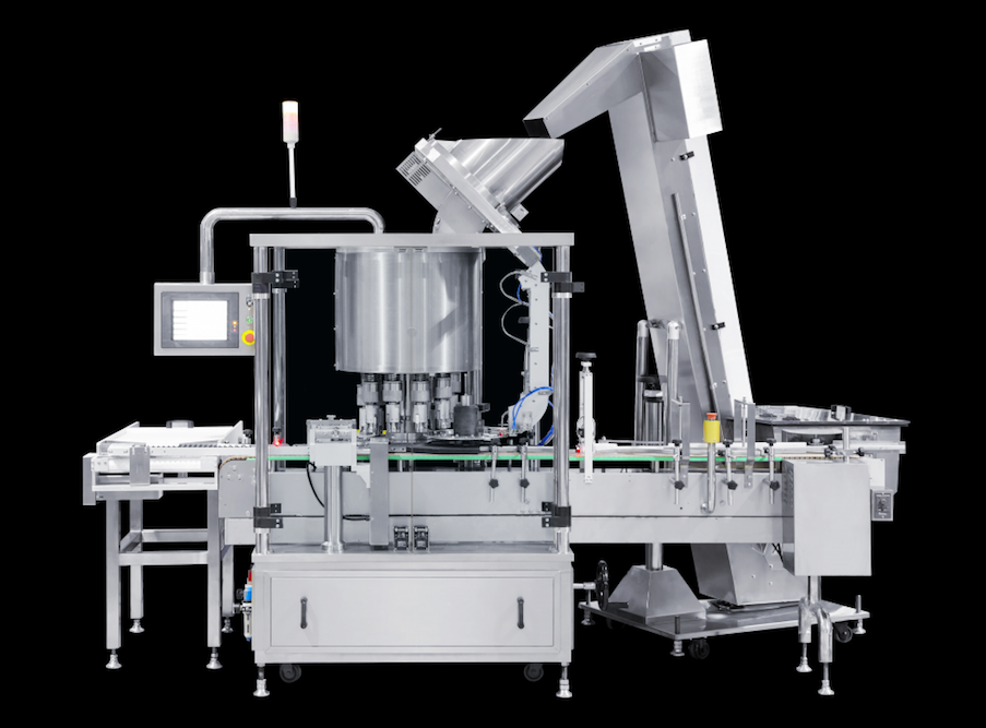
Fully Automatic High-Speed Rotary Trigger Cap Capping Machine Relevant when a rotary trigger-capping layout is being considered. Confirm the intended feeder, bottle control, cap orientation and SKU compatibility for the quoted machine. |
7. Send Complete Samples and Ask for a Test That Reproduces Real Feeding Conditions
A trigger cap feeding sample test is only useful when the samples represent production. One cap and a dimensional drawing may help with basic geometry, but they cannot show bulk interaction, repeated tube crossing, accumulated pressure or how a group of trigger heads behaves during restart.
|
Physical samples to send
|
Production information to send
|
What the test video should prove
Ask for a view of the complete sequence rather than only the capping head. The most useful video follows the trigger from initial presentation through orientation, transfer and placement so that the first loss of control is visible if a problem occurs.
1. Steady feeding: verify that the required trigger direction is maintained across repeated cycles.
2. Normal accumulation: watch whether heads or tubes begin to hook, cross or change attitude as the queue builds.
3. Stop and restart: check whether accumulated closures release cleanly after a short interruption.
4. Low-cap condition and recovery: observe what happens when the feed level drops and then replenishes.
5. Final insertion: confirm that the tube approaches the bottle opening through a repeatable path before the cap reaches its starting position.
If missing-cap or orientation detection is included in the proposed configuration, the test should also identify the fault being simulated and show the expected machine response. Do not assume that a detection function demonstrated on one machine is included in another quotation.
Buyer recommendation: send the complete cap assembly, dip tube and representative bottle samples, and describe both the incoming cap condition and the required orientation. Any proposed feeding method should be confirmed for the actual equipment through a sample trial rather than approved from a generic trigger-cap description.
8. Turn the Feeding Requirement Into a Useful Quotation Request
A productive inquiry should describe the handling problem, not simply request “an automatic trigger cap feeder.” State the trigger and bottle combinations, the complete dip tube condition, how closures arrive at the machine, the required direction at placement, the expected SKU sequence and the desired level of automation.
If finished-bottle nozzle direction matters for labeling, carton loading or shelf presentation, identify that as a separate requirement. Feed orientation and final capped orientation are related, but they are not necessarily the same mechanical task.
This approach avoids two specification mistakes: choosing a feeder because it handles a visually similar trigger, and choosing the capper before proving that the closure can reach it in a repeatable usable condition. The feeding route and the capping process should be evaluated as one connected handling sequence.
Continue with the pages that match the next decision
Trigger Cap Capping Machine for Spray Bottles →
Use this for the broader trigger-sprayer capping application after the feeder question has been defined.
Cap Feeding Reliability Troubleshooting →
Use this when a feeding path already exists and the problem is repeated misfeeds, jams or unstable transfer.
Choose the feeding concept after the real closure has been reviewed
Compare the available trigger-cap handling approaches with the complete assembly in mind. When the project reaches technical review, send representative caps, production-length dip tubes and bottles so the proposed trigger cap feeding and capping configuration can be evaluated against the actual package.
| Review Automatic Trigger Cap Feeding & Capping | Send Caps, Dip Tubes & Bottles for Testing |
Frequently Asked Questions
Can two trigger sprayers with the same bottle thread use the same cap feeding setup?
Not necessarily. The thread may be identical while trigger balance, nozzle projection, head geometry, tube length or tube flexibility differs. Those characteristics can change sorting and transfer behavior, so complete samples should be compared before compatibility is confirmed.
Can trigger cap feeder compatibility be approved from drawings alone?
Drawings are useful for dimensions and likely clearance points, but they do not fully show center-of-gravity behavior, surface interaction, residual tube curvature or how several closures behave together. Physical samples provide a stronger basis for feeding validation.
Should every SKU be included in the sample trial?
Include every materially different trigger-and-bottle combination expected on the equipment, especially formats with different tube lengths, head geometry or direction requirements. The most difficult SKU should be included rather than testing only the easiest format.
Does changing the bottle affect the cap feeding method?
It can affect the final placement condition even when the trigger itself is unchanged. Neck position, opening, neck finish, shoulder shape and container stability can influence tube entry and initial closure seating, so the bottle should be included in compatibility testing.
Is pick-and-place automatically better for long dip tubes?
No. Controlled pickup may help in some applications, but the trigger still has to arrive at the pickup point consistently and the tube still needs a reliable insertion path. Pick-and-place controls the placement stage; it does not replace the need for suitable upstream supply and presentation. The method should be chosen from actual sample behavior rather than tube length alone.
What should procurement request before approving automatic trigger cap feeding?
Request a sample-based review that shows orientation, dip tube behavior, transfer and placement with representative closures and bottles. The quotation should also identify the agreed orientation requirement, included detection functions and the proposed response to relevant feeding faults.