
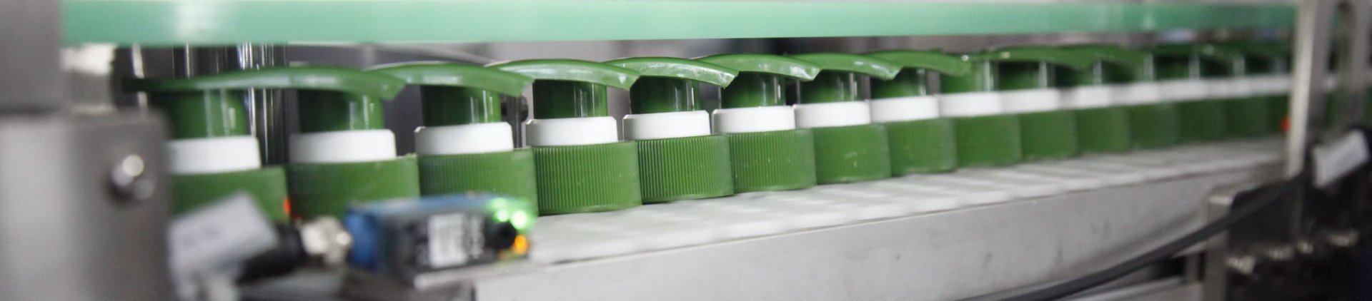
Quick answer: choose between a rotary capping machine and an inline capper from the production job, not from the machine label. Rotary architecture deserves early attention when the line needs high sustained bottle output, long production campaigns and controlled bottle positioning. Inline capping is often the more practical starting point when compatible formats change frequently and straight-through conveyor flow matters. If bottle stability, closure feeding or placement is uncertain, samples should decide the machine architecture before a purchase order does.
The key buying question is not “Which capper has the higher nameplate speed?” It is “Which capper can keep producing acceptable finished bottles with this bottle, this closure, this cap-feeding method and this changeover pattern?”
1. Start With the Production Job, Not the Capper Type
Procurement usually enters the discussion with a target in bottles per minute. That number matters, but it is only useful when everyone means the same thing by “output.” A short peak during a clean demonstration is different from the sustainable finished-bottle rate required through normal cap replenishment, small stops, bottle variation and SKU changes.
Three inputs narrow the selection quickly:
|
Required finished outputDefine the rate the connected line must maintain, not a short isolated peak.
|
Changeover patternRecord how often the bottle, cap or both change during normal production.
|
Package stabilityFlag tall, light, flexible, irregular or orientation-sensitive bottles early.
|
Investigate rotary first when high sustained output and long runs dominate
A rotary capper becomes increasingly relevant when production is repetitive and the package benefits from defined positions through the capping process. The case becomes stronger when active capping capacity is genuinely limiting finished output and the surrounding line can continuously supply bottles and closures.
Investigate inline first when compatible formats change more often
An inline capper can be attractive when the required output can be achieved on a straight conveyor path and reducing format-specific transfer work matters to the production schedule. A simpler flow path does not remove the need for bottle restraint, cap presentation and stable tightening, but it can make format handling easier to evaluate.
Use that screening before comparing bottle capping machines. The equipment discussion is much more productive once target output, bottle behavior, closure type and changeover frequency are already defined.
2. Compare Bottle Control, Output and Cap Feeding Together
The decisive mechanical difference is not whether the machine looks round or straight. It is how the bottle is controlled while the closure is presented, engaged, tightened and discharged. A bottle that caps easily by hand can still be difficult to automate when the line adds speed, side pressure, transfer points and repeated start-stop conditions.
|
Rotary bottle motionBottles move through coordinated positions around a rotating working section. Entry, spacing, transfer and each working position must stay synchronized with the package geometry.
|
Inline bottle motionThe package moves substantially along the conveyor direction. Guide position, bottle restraint, spacing and the tightening mechanism must work without losing stability.
|
This changes what should be inspected. On a rotary machine, ask how reliably the bottle enters the rotating section, stays located at the working position and transfers back out. On an inline machine, ask whether the bottle remains upright, correctly spaced and sufficiently restrained while moving through the capping zone.
Tall narrow containers may lean as side pressure changes. Flexible bottles may deform under restraint. Irregular bottles may rotate or present inconsistently. The correct architecture is the one that controls those behaviors without creating another bottleneck.
| Selection factor | Rotary capper | Inline capper |
|---|---|---|
| Output | Strong candidate when sustained capping demand is high and the connected line can feed continuously. | Practical when the target line rate is stable through straight-through movement and the selected tightening process. |
| Bottle stability | Defined positions can provide deliberate control, but transfer parts must suit the actual bottle. | Side restraint, guides and spacing deserve close attention with tall, light, flexible or irregular bottles. |
| Closure type | Feeding, placement and head configuration must match the closure and any orientation requirement. | Simple threaded closures suit continuous inline tightening more easily than complex asymmetric closures. |
| Cap feeding | The feeder must keep enough correctly oriented closures available for the rotary process. | The same rule applies inline; inconsistent cap delivery can become the real bottleneck. |
| SKU pattern | Long runs can justify dedicated bottle-control parts and more setup work. | Frequent compatible format changes can favor a simpler straight-through arrangement. |
Cap feeding is part of the output calculation. Sorting, orientation, transfer and cap presentation must support the same production rhythm as the capping mechanism. Buying more capping capacity does not solve closure starvation.
Closure geometry can change the decision even when bottle output stays the same. A round threaded cap presents a different feeding problem from a pump or trigger with a long dip tube and an asymmetric head. Review how different closure types change capper setup before treating every planned SKU as a simple size adjustment.
3. Use Changeover, Footprint and SKU Pattern to Choose the Architecture
Floor space should be reviewed as a working line layout, not only as the machine frame dimensions. A rotary machine concentrates capping around a rotating section, but the project still needs infeed and discharge transitions, cap-feeding equipment, change-part access and maintenance clearance. Inline equipment follows the conveyor direction more naturally, yet feeders, accumulation and operator access still consume usable floor space.
Measure the complete stop-to-stable-output changeover
A high-SKU plant should not compare changeover by asking only how quickly one adjustment can be moved. Record what physically changes and how much work is required before acceptable production is restored.
- Parts replaced: guides, bottle-transfer components, holders, closure-contact parts or other package-specific items.
- Settings reset: height, spacing, restraint, feeding and capping adjustments for the next SKU.
- Verification work: the trial bottles and checks required to confirm stable feeding, cap placement and capping after the change.
- Operator intervention: bottle straightening, cap corrections or repeated recoveries that continue after the formal changeover is supposedly complete.
This is why an inline capper for frequent changeovers should be selected from the real SKU matrix rather than a generic flexibility claim. Two similar screw-cap formats may require little work, while a switch involving a very different bottle shape or closure can change the handling problem completely.
Projects where rotary deserves priority
Rotary architecture deserves closer evaluation when sustained high-output demand, long production runs and controlled bottle positioning carry the most weight. It is especially relevant when the package needs more deliberate handling and the active capping process is truly limiting finished output. Exact suitability still depends on the bottle, closure and feeding method.
Projects where inline deserves priority
Inline architecture deserves closer evaluation when the line can meet the required output without rotary transfer and straight-through bottle movement reduces format-specific work. Frequent compatible SKU changes can strengthen that case, provided bottle restraint and closure presentation remain stable at the target rhythm.
Situations where neither choice should be approved yet
Do not approve an architecture when bottle stability, cap orientation, dip-tube entry, final closure direction or upstream supply behavior is still uncertain. Those are not details to solve after purchase; they can determine the handling system itself. The safest next step is sample testing under the intended production rhythm.
Risk to avoid: do not “upgrade to rotary” simply because management wants more speed. If the actual loss is closure starvation, poor bottle spacing or repeated micro-stops, a faster capping mechanism may only move the bottleneck. Use filling and capping line bottleneck analysis to separate active capping capacity from waiting, blocking and transfer losses.
4. Validate the Choice With Real Bottles, Caps and Production Rhythm
Drawings are useful for dimensional screening, but physical samples reveal behaviors that drawings cannot fully describe. A bottle may lean under guide pressure, a flexible sidewall may deform, or a trigger closure may feed inconsistently because of its shape and dip tube. A meaningful trial follows the complete capping path instead of proving only that one cap can be tightened.
| 01 | Feed and orient. Observe whether closures arrive in a repeatable orientation and whether the feeder can keep the capping process supplied. |
| 02 | Control the bottle. Watch entry, spacing, restraint and transfer for leaning, rotation, deformation or inconsistent presentation. |
| 03 | Place the closure. Confirm that the cap reaches the bottle correctly before significant tightening force is applied. |
| 04 | Tighten and discharge. Check the finished closure and the bottle behavior leaving the working area, not only the motion of the capping head. |
| 05 | Stop and restart. Include normal interruptions. A machine that works only during an uninterrupted demonstration has not been fully validated. |
| 06 | Change an important SKU. Record the parts, settings and recovery work needed before the next bottle-and-cap combination reaches stable production. |
Test the difficult package, not only the easy one. For a multi-SKU project, include the routine high-volume format and the bottle or closure expected to be most demanding. The tallest bottle, softest container, longest dip tube or most asymmetric closure can determine the required handling system.
The test pace matters too. Successful capping at a comfortable demonstration speed does not prove the machine can maintain the target cycle. Validation should show that bottle control, cap feeding, placement and discharge stay stable at the production condition the line actually requires.
Three buying rules to keep the comparison honest
- Compare sustainable finished output, not a short demonstration peak. Include normal cap replenishment, small stops and the connected line around the capper.
- Compare the hardest approved SKU, not only the easiest sample. A difficult bottle or closure often exposes the handling requirement that determines the final architecture.
- Compare repeatable changeover, not expert setup time. The useful measure is stop-to-stable-output with documented parts, settings and acceptance checks.
5. Review Relevant Equipment and Prepare a Better RFQ
Product pages are most useful after the selection logic above has narrowed the problem to a realistic machine direction. The two options below represent different capping approaches that are directly relevant to an inline-versus-rotary comparison. They are references for configuration review, not substitutes for bottle-and-cap validation.
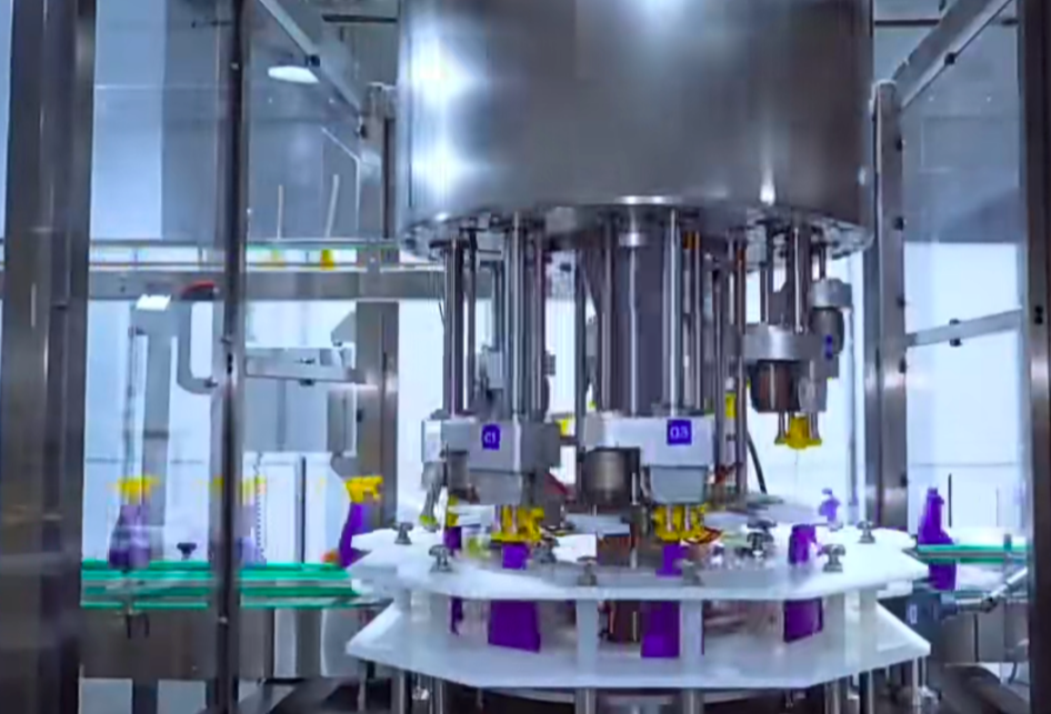
High Speed Rotary Type Trigger Sprayer Capping MachineFits: trigger-sprayer projects where rotary handling and continuous line integration are being evaluated. Why relevant: the product page describes a rotary design with a constant-torque rotating cap mechanism. Confirm first: actual trigger geometry, bottle control, cap feeding and target production rhythm with samples. |
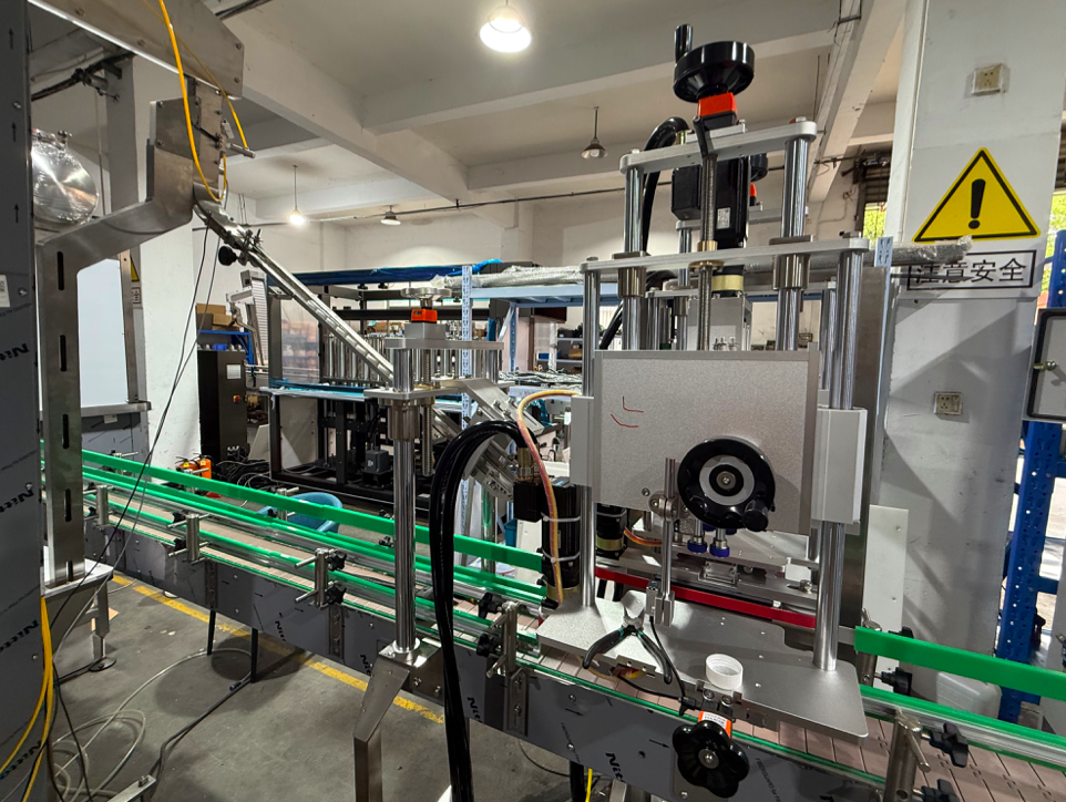
High Speed Automatic Screw Capping MachineFits: continuous inline screw-capping projects where straight-through integration is important. Why relevant: the product page describes cap feeding, positioning and screw tightening in one continuous inline workflow with servo torque control. Confirm first: bottle and threaded-cap combinations, line interface, format changes and required output. |
RFQ data that makes capper selection more accurate
An RFQ containing only “automatic capper required” and a speed target leaves too much undefined. The useful data explains the production problem and the package the machine must control.
- Required sustainable bottle output and any separate short-term peak requirement.
- Bottle drawings, representative samples, dimensions, material and known stiffness or stability problems.
- Closure drawings and physical samples, including screw cap, pump, trigger or other closure type.
- Dip-tube details where applicable, plus cap-feeding and orientation requirements.
- Number of bottle-and-cap combinations, normal changeover frequency and highest-volume SKUs.
- Existing filler and downstream equipment, conveyor direction and usable floor space.
- Known accumulation or transfer problems and any required finished closure orientation.
- Layout drawing and a production video when handling behavior is difficult to describe.
That information allows engineering teams to compare architectures around the real production condition rather than selecting from nominal speed alone. It also exposes early whether the project needs a simple format adjustment or a fundamentally different bottle- and closure-handling approach.
Related reading
Different Closure Types and Capper Setup
Use this when screw caps, pumps or triggers may change feeding, placement or format requirements.
Filling and Capping Line Bottleneck Analysis
Use this when the line is missing its output target and the team needs to confirm whether capping capacity is actually the constraint.
Choose From Verified Production Conditions, Not Nameplate Speed
Provide target BPM, bottle stability, closure type, changeover frequency and available floor space before deciding between architectures. If the choice is close, use bottle and cap samples to confirm feeding, bottle control, placement, tightening and restart behavior before final approval.
| Review Capping Options | Send Project Data for Review |
6. Frequently Asked Questions
Can bottle output alone determine whether I need a rotary capper?
No. Output is an important first filter, but bottle stability, closure geometry, cap feeding, changeover frequency and line integration can change the decision. Compare sustainable finished output under normal production conditions rather than a short peak speed.
What should I test if both rotary and inline machines appear capable of the target speed?
Focus on the conditions that separate the architectures: bottle stability at the infeed and capping zone, closure orientation, stop-and-restart behavior, changeover work and the ability of the feeder to sustain the target rhythm.
What samples should be supplied for capper testing?
Provide representative production bottles with matching closures for the important SKUs. Pump and trigger projects should include the complete closure assembly and normal dip-tube condition. Include both the routine high-volume package and any format expected to be difficult to feed or stabilize.
Can one capper run several bottle and closure sizes?
Possibly, but compatibility should not be assumed from diameter ranges alone. Different formats can require changes to guides, bottle control, feeding components, closure-contact parts or machine settings. Confirm each important bottle-and-cap combination before purchase.
What should be validated before issuing a purchase order?
Confirm representative bottle and cap handling, feeding stability, target production rhythm, capping result, stop-and-restart behavior, required change parts and line-layout interfaces. Any uncertain compatibility should be resolved through sample testing or technical confirmation before the final configuration is approved.