
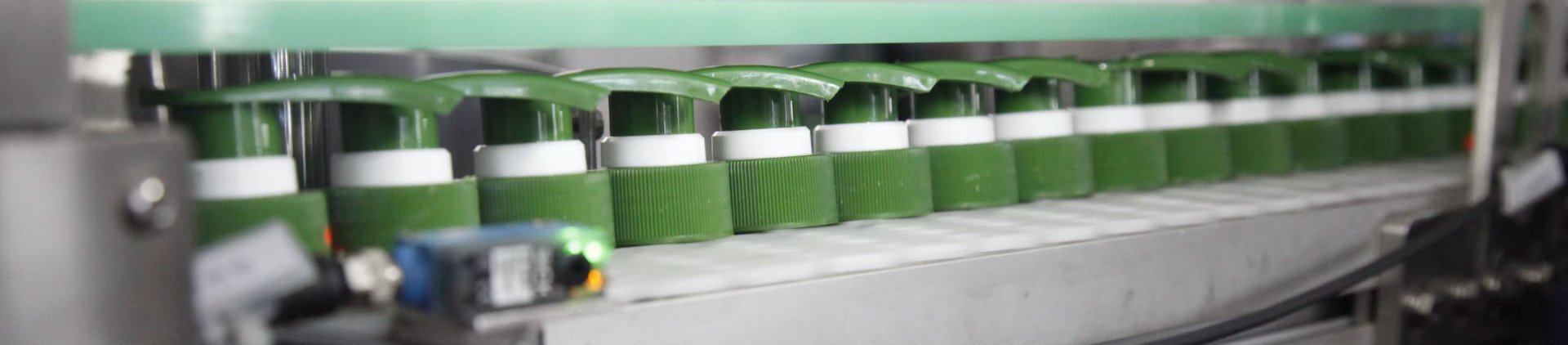
Improving cap feeding reliability rarely starts at the point where the line finally stops. A reversed closure may leave the sorter incorrectly, a correctly oriented cap may turn during transfer, or a stable queue may lose control only when it reaches the placement point. In an automatic capping machine, these events belong to one connected path: sorting → transfer → chute or track → placement.
That distinction matters on a running packaging line. When several caps suddenly pile up near the bottle, adjusting the final guide may clear the immediate stop while leaving the original fault untouched. A better diagnosis follows the closure from loose bulk supply to the bottle neck and identifies the first point where normal movement changes.
Operational focus: Treat cap feeding as a sequence of mechanical events. Separate sorting errors, transfer instability, chute pressure, spacing variation, and placement timing before several machine settings are changed at once.
Identify Where the Feed Failure Starts
A cap can stop at the end of a chute even though the first abnormal event happened much earlier. One closure may hesitate at a transfer joint. The next closure pushes against it, pressure builds, and the visible jam develops several positions downstream.
The useful question is not simply where the caps stopped. Instead, look for the first difference between a normal cycle and a failed cycle. That difference may be a tilt, short hesitation, unexpected rotation, growing gap, or sudden change in queue pressure.
Break the feed path into observable zones
Troubleshooting becomes easier when each function has a clear boundary. Although mechanical layouts vary, most cap feeding systems can still be followed as a sequence rather than treated as one large mechanism.
Follow the closure through these points:
- Loose bulk cap supply and initial presentation.
- Sorting and orientation.
- Sorter discharge and first transfer.
- Elevator, conveyor, chute, rail, or guide transition.
- Accumulation before separation.
- Cap spacing and individual release.
- Bottle arrival and final cap placement.
During a production stop, the final pile of closures attracts attention first. However, the pile only shows where the problem finished. Several successful and failed cycles usually reveal an earlier movement change that provides a better starting point.
Use the symptom to narrow the search
Different symptoms suggest different areas to inspect. Even so, a symptom should guide observation rather than become an automatic diagnosis. A feed gap, for example, can come from poor sorting, a slow transfer, excessive friction, or a restriction farther downstream.
| Observed condition | Inspect first | Compare |
|---|---|---|
| Upside-down or reversed caps | Sorting and sorter discharge | Orientation before and immediately after exit |
| Repeated jam at one transition | Guide joint or support change | Clearance, contact point, tilt, and local pressure |
| Caps arrive in clusters | Upstream track movement | Short hesitation followed by sudden release |
| Stable feeding until restart | Accumulation and release zone | Queue before the stop and first restart cycles |
| Cap arrives but misses the bottle | Placement and bottle arrival | Release moment versus bottle position |
Slow-motion video is especially useful here. A still image shows where a cap ended up, while video shows how it reached that position. That difference can prevent a local adjustment from masking an upstream fault.
Cap Geometry and Orientation Stability
Two closures can look almost interchangeable on a dimension sheet and behave very differently in loose bulk. A flange, pump head, trigger projection, rib, flexible section, or shifted center of mass can change the position a closure naturally chooses.
Changing caps should not be treated as a diameter adjustment alone. The more useful question is whether the new closure can remain in the required orientation while it is supported, pushed, accumulated, transferred, and released.
Read cap geometry as a handling shape
Place several loose caps on a flat surface without forcing a preferred position. Then compare the positions that appear repeatedly. A symmetrical screw closure may produce a simple pattern, while an irregular dispensing closure can settle into several mechanically stable attitudes.
This basic observation gives a clearer picture of the sorting challenge. If an unwanted position is naturally stable, the sorting mechanism needs a reliable way to reject or redirect it. A cap that balances easily on one edge may also become vulnerable when support narrows during transfer.
Look beyond nominal dimensions. A useful cap review considers the complete handling shape. Overall height and outside diameter matter, but so do the surfaces that actually touch rails, guides, belts, neighboring closures, and separation components.
- Skirt, flange, collar, and shoulder geometry.
- Pump heads, trigger bodies, nozzles, and other projections.
- Areas that can flex when several caps press together.
- Ribs, texture, or surfaces that affect sliding behavior.
- Features that can nest, overlap, hook, or interlock.
- Balance when support changes from one surface to another.
A cap can travel calmly across a fully supported section and then rotate as soon as one side loses support. The heavier side drops first, and the same tilt may repeat at the same joint. Opening the entire track would not address that specific behavior.
Surface condition matters as well. Texture, molding condition, dust, or residue can change how easily a closure slides. Representative physical samples are therefore useful when a new cap behaves differently from an existing stable format.
Unscrambler / Elevator and Transfer Consistency
Sorting creates the required orientation, but reliable feeding also depends on what happens immediately afterward. A closure can leave the sorter correctly and still turn, bounce, or lose support during the first handoff.
For irregular dispensing closures, a cap unscrambler can form part of the handling strategy. Even then, sorter performance should be reviewed separately from transfer stability and final placement.
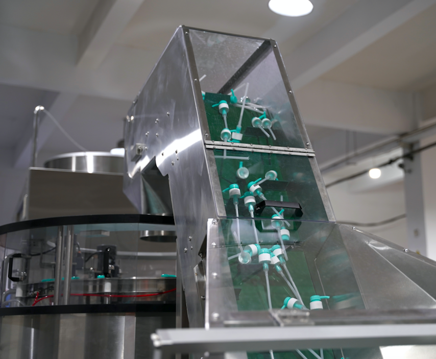
This Runtech feeding-elevator view shows dispensing closures being carried through an actual transfer stage, making it relevant to orientation and handoff review. Actual closure samples are still needed to confirm how a specific cap behaves through the full feed path.
Separate feeder output from downstream restrictions
When the placement point runs empty, increasing upstream activity can appear to be the obvious response. Sometimes that helps. In other cases, it simply adds pressure behind a downstream restriction.
Watch the queue between the sorter and the shortage point before changing output. If correctly oriented caps are already waiting upstream, sorter capacity may not be the limiting factor. The transfer or chute should then receive closer attention.
A useful transfer check:
Keep the final sorter movement and first downstream guide in the same video frame. If the cap changes angle exactly as support changes, inspect the handoff. If orientation is already wrong before that point, the sorter remains the earlier failure stage.
Judge restart behavior, not only steady running
A feed stream can appear stable after several minutes of continuous operation. A brief line stop changes the condition. Caps may pack more tightly against a stop, contact positions can shift, and the first closure after restart may carry more pressure.
Repeated stop-and-restart cycles expose this behavior quickly. If the first few caps regularly tip or jam, the issue may concern accumulated pressure and release rather than general sorting.
Temporary starvation creates another useful test condition. When an almost empty track begins filling again, large gaps can reach the release point before a stable queue forms. Reliable feeding should recover without repeated manual clearing.
Chute, Track, Back Pressure and Cap Spacing
Once a closure enters a single-file path, the task changes from orientation to controlled movement. The track must preserve cap attitude while allowing enough freedom for a continuous supply. Too much freedom can allow rotation, while excessive restriction can create friction or wedging.
This balance becomes more important when several caps accumulate. A guide that works with one isolated closure may behave differently when a full queue pushes from behind. Both free movement and accumulated movement need to be observed.
Inspect transitions before long straight sections
Long straight rails are usually easy to observe. By contrast, many repeated feeding faults develop where geometry changes: guide joints, curves, slopes, width changes, support changes, and entrances to separation or placement areas.
A small step can create a short hesitation. One cap pauses, the following cap closes the gap, and a cluster begins to form. By the time that cluster reaches the separation point, the original hesitation may be several positions behind.
Back pressure is a condition, not a cure. A continuous queue often includes contact between neighboring caps. Greater pressure is not automatically better. An irregular closure can tilt under compression, while flexible features can overlap or catch one another.
At the other extreme, large uncontrolled gaps can leave no closure available when the next bottle enters the placement station. The goal is a predictable queue that remains stable through normal starts, stops, and changes in downstream demand.
A practical cap-spacing check
- Watch upstream: Does one closure pause before a cluster forms?
- Watch accumulation: Do caps stay aligned as queue pressure increases?
- Watch separation: Does one closure release cleanly at a time?
- Watch feed gaps: Does supply recover after temporary starvation?
- Watch restart: Does the first release behave differently after a stop?
A healthy buffer and a compressed queue are not the same condition. A useful buffer stores available caps while preserving controlled movement. A tightly compressed queue stores force, which can be released suddenly when the downstream stop opens.
Adjust guide clearance without losing orientation control
Increasing clearance can remove a hard interference. Extra space may also allow more rotation or lateral movement. The adjustment should identify which contact surface needs additional space and which surfaces must continue controlling orientation.
The opposite is equally important. Tight guides can improve positional control but may increase friction and sensitivity to normal cap variation. Stable feeding usually requires controlled freedom rather than maximum restriction.
Placement Timing vs Bottle Arrival
A correctly oriented cap can still miss the bottle. At the placement point, two streams must meet. The closure needs to arrive in a controlled position, while the bottle neck must reach the same area at the expected moment.
A missed placement should not be diagnosed from cap movement alone. Bottle stability, guide contact, neck position, and spacing can all move the effective meeting point.
Watch the cap and bottle in the same frame
A useful side-view recording begins before the bottle enters the placement zone. It should also show the final part of the cap track. Several correct and incorrect cycles can then be compared without relying on memory.
If cap arrival remains repeatable while the bottle neck changes position, container handling may require attention. Conversely, stable bottle movement paired with irregular cap arrival points toward feed spacing, separation, or an upstream hesitation.
When a cap misses the bottle, compare four moments:
- Cap position immediately before release.
- Bottle neck position before contact.
- The first moment of cap-to-bottle contact.
- Cap attitude immediately before tightening.
Separate placement from final tightening
A closure that reaches the tightening station at an angle creates an unstable starting condition. Changing the tightening mechanism may reduce the visible defect, but it cannot make an inconsistent placement event repeatable.
Stable placement should be confirmed first. Only then does it make sense to evaluate downstream tightening as a separate function.
How to Test a New Cap
A new closure should be treated as a moving handling part, not only as a drawing. The useful test is not one long uninterrupted run; it is a comparison of how the cap behaves before it enters the line, while it moves through the feed path, and when it finally meets the intended bottle.
That structure makes it easier to see whether a new problem begins in bulk handling, sorting, transfer, accumulation, or final placement.
Before the line test: understand the closure itself
If an existing cap already runs reliably, use it as the reference. Compare resting positions, projections, support surfaces, flexible sections, sliding behavior, and cap-to-cap contact rather than looking only at outside diameter and overall height.
Then observe several loose caps together. Nesting, interlocking, stacking, and repeated resting positions often appear only in realistic bulk conditions, especially with pump, trigger, nozzle, or other projecting features.
During feeding: separate orientation from movement
Confirm that the sorter produces repeatable orientation before increasing downstream demand. If incorrect caps still leave the sorter, a faster feed rate only makes the failure harder to interpret.
Once sorting is stable, follow the cap through discharge, transfer, low accumulation, normal accumulation, stop-and-restart cycles, and recovery after temporary starvation. The important question is whether each handoff preserves the orientation created upstream.
At the bottle: finish with the real placement condition
A closure that travels cleanly through the track can still behave differently when it meets the bottle. Final testing should therefore use the intended container and the actual placement condition, not an empty feed path alone.
The useful endpoint is stable orientation, controlled release, consistent bottle arrival, and repeatable placement before tightening begins. That is a stronger approval point than simply confirming that the cap reaches the end of the chute.
A useful comparison: a new cap may pass a sorter-only test yet fail under queue pressure, or move well through the chute yet miss the bottle. Approving each stage separately makes it easier to identify where compatibility actually changes.
How to Verify That Cap Feeding Reliability Has Improved
An adjustment should not be accepted simply because one visible jam disappears. A useful improvement should survive the same operating condition that exposed the problem and should not move the failure to another point in the feed path.
Use the original failure as the baseline, change one major variable, and repeat the same cap, bottle, line-speed, accumulation, and restart conditions as closely as practical. The result should be judged by what the feed path now does, not only by whether the machine ran longer.
The original fault no longer repeats
The same hesitation, tilt, reversal, cluster, or placement miss should disappear under the operating condition that previously exposed it.
Recovery remains controlled
Stop-and-restart cycles and temporary starvation should recover without tipping, wedging, sudden compressed release, or repeated manual clearing.
No new weak point appears downstream
Normal accumulation should remain stable, and the closure should still reach the bottle in a repeatable attitude before tightening begins.
The acceptance limit should come from the actual production requirement rather than an arbitrary universal number. A high-speed line may need a different run length or interruption tolerance from a lower-output machine. What matters is that the agreed operating case can be repeated with stable feeding, predictable recovery, and no new failure stage.
For a new closure format, repeat the confirmation with representative production samples or lots after the controlled baseline test. This helps separate a one-time adjustment success from a feed path that remains sensitive to normal cap variation.
Data and Samples for Feed-System Review
A useful engineering review needs enough information to reproduce the failure. One cap photograph rarely shows the conditions that create a jam, reversed orientation, feed interruption, or unstable placement.
The information package should describe the closure, loose-bulk state, intended feeding requirement, failure position, and bottle arrival condition. Physical samples can then be used to reproduce the actual handling behavior.
Build an evidence package that can reproduce the failure
A dimension drawing should show geometry that can influence contact and support. Depending on closure design, useful information may include overall height, maximum width, skirt, flange, collar, actuator, nozzle, trigger body, and other projecting features.
The drawing establishes the geometry. Actual closures then show balance, surface behavior, flexible movement, assembly variation, and interaction with neighboring caps.
Record the fault before the machine stops. Video of a stationary jam shows the result but rarely shows the cause. Recording should begin several cycles before the failure and continue until the problem becomes visible.
Where practical, record the same failure more than once. A fault that always starts at one joint suggests a different investigation from a problem that appears at changing locations.
Prepare these materials for a feed-system review
- Representative physical cap samples.
- Cap dimension drawing or marked measurement sheet.
- Video showing caps in the normal loose-bulk supply condition.
- Video showing the jam, reversal, feed gap, or unstable release location.
- Several feed cycles before the visible failure.
- Intended cap-feeding rhythm or bottle-arrival rhythm as a project requirement.
- Bottle samples or drawings when the issue reaches placement.
- Side-view footage showing bottle arrival and cap placement together.
- A short baseline-versus-adjusted record showing what changed and whether the original failure repeated.
Compare stable and unstable conditions one variable at a time
The strongest troubleshooting evidence often comes from direct comparison. A stable cap lot can be compared with a problematic lot. The same closure can also be recorded before and after one clearly defined adjustment.
Whenever practical, change only one major variable at a time. If guide position, feeder activity, sensor settings, and release timing all change together, the line may improve while the reason remains unclear.
Keep a short failure record. A compact record prevents the same adjustment from being repeated and makes recurring patterns easier to compare across cap lots and test conditions.
Cap / lot
Identify which physical samples were used.
First abnormal point
Record where normal movement first changed.
Queue / restart condition
Note whether the fault occurred in steady flow, accumulation, or restart.
Adjustment / result
State what changed and whether the original fault repeated.
Turn a Cap Feeding Fault Into a Testable Problem
Reliable cap feeding comes from a chain of stable events. Sorting creates the required orientation, transfer preserves it, the chute manages movement and accumulation, and placement brings the closure and bottle together consistently.
Once the first abnormal point is clear, the next step is not another broad machine adjustment. It is a controlled comparison using the actual cap, bottle, feed condition, and failure evidence.
For a technical review, prepare representative cap samples, a dimension drawing, loose-cap supply footage, video beginning several cycles before the failure, the intended feed or bottle-arrival rhythm, and the relevant bottle information. If an adjustment has already been tested, include a short baseline-versus-adjusted comparison so the review can focus on the stage that actually changed.
Frequently Asked Questions
Why can the same feed system become unstable after changing to another cap?
A feeding system responds to the complete handling geometry, not only nominal cap diameter. Changes in balance, flange shape, surface friction, projections, flexible parts, or natural resting position can alter sorting and transfer behavior. A new format should be compared with a known stable closure before broad mechanical adjustments are made.
Where should cap feeder troubleshooting start when the jam location is obvious?
Start slightly upstream from the visible blockage. Several caps may finally stop at one position even though the first hesitation, tilt, or spacing change happened earlier. Compare successful and failed cycles to locate that first repeatable difference.
Can cap orientation compatibility be confirmed from drawings alone?
A drawing can confirm major geometry and likely clearance points, but it cannot fully reproduce balance, sliding behavior, flexible movement, loose-bulk interaction, or behavior under accumulation. Physical closure samples provide the stronger basis for a feeding test.
What samples and videos are useful for a cap feeding test?
Useful materials include representative physical caps, a dimension drawing, the intended bottle, footage of the normal loose-cap supply condition, and video showing several cycles before the failure. The intended feed rhythm and bottle-arrival condition should also be provided so the test reflects the actual operating case.
Why can cap feeding become unstable only after a stop and restart?
A pause changes the condition of the queue. Caps can accumulate more tightly against a stop, support positions may shift, and the first release after restart can behave differently from continuous flow. Restart behavior should therefore be included in the feed test rather than judged from steady running alone.