
A pump cap and a trigger cap can both include a threaded collar and a dip tube, but they do not behave the same way during placement, tightening, orientation, or discharge. A pump cap vs trigger cap capping machine decision should begin with the complete bottle-and-closure combination rather than the cap diameter alone.
Pump closures place more attention on tube entry, collar gripping, actuator protection, and possible dispenser direction. Trigger sprayers add an offset handle and nozzle, which increase side-clearance, bottle-support, cap-feeding, and packing-direction requirements. The practical choice depends on the real bottle, final closure, filled-product behavior, output target, and required level of automation.
Quick answer:
Choose pump-cap handling when the main risk is guiding a long tube into the bottle and tightening the collar without damaging the actuator. Choose trigger-cap handling when the sprayer handle, nozzle direction, wider head, or shaped bottle requires more clearance and orientation control. A flexible system may support both only within a confirmed bottle-and-cap range with suitable change parts and sample testing.
Jump to: Core Differences · Pump Caps · Trigger Caps · Applications · Torque & Orientation · Machine Selection · Sample Checklist · FAQ
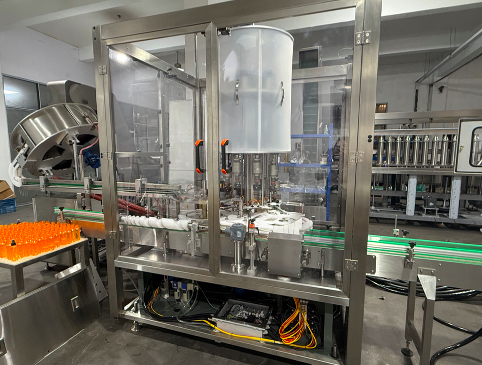
Pump Cap Tightening
Best reviewed around dip-tube insertion, pump-collar grip, actuator protection, bottle centering, and the required finished dispenser direction.
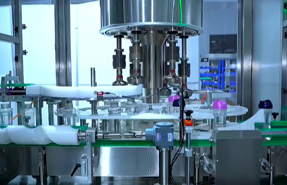
Trigger Cap Tightening
Best reviewed around tube entry, sprayer-head clearance, nozzle direction, shaped-bottle support, cap feeding, and smooth downstream discharge.
Pump Cap vs Trigger Cap Capping Machine: Core Differences
The two closures share some basic requirements: the tube must enter the bottle cleanly, the first thread must engage straight, the bottle must stay centered, and the final tightening condition must be repeatable. Their upper structures create different mechanical priorities.
| Decision Point | Pump Cap | Trigger Cap |
|---|---|---|
| Main upper structure | Vertical actuator, threaded collar, and dip tube. | Offset handle, nozzle, threaded collar, and dip tube. |
| Primary handling risk | Tube catches the neck or the tightening head contacts a weak or visible pump part. | Handle or nozzle interferes with rails, nearby bottles, guards, or packing flow. |
| Bottle support | Stable neck centering while the tube enters and the collar begins threading. | Firm side support for round, oval, flat, grip-style, or offset-neck spray bottles. |
| Direction requirement | May need a locked shipping position or front-facing actuator. | Often needs a packing-friendly or label-facing nozzle and handle direction. |
| Cap feeding | Long tubes and moving actuators may complicate sorting and transfer. | Handles, nozzles, and tubes may interlock or require a defined presentation angle. |
A cap that falls within a stated diameter range is not automatically compatible with a machine. The bottle wall, neck finish, shoulder shape, closure geometry, tube length, thread quality, and downstream direction must work together during a repeated production cycle.
Pump Cap Capping Machine Requirements
Pump-cap tightening starts before the collar turns. The dip tube must enter the bottle opening without folding against the neck, catching the shoulder, or pushing the closure into a tilted position. Tall or lightweight bottles may also move when the tube enters or when downward pressure is applied.
The tightening head should contact a stable area of the closure. Depending on the pump design, that may be the threaded collar, a ribbed edge, or another confirmed gripping surface. Contact with the actuator, decorative surface, locking nozzle, or other movable area can mark the closure or prevent the intended tightening action.
Filled bottles are more useful than empty display samples during testing. Lotion, shampoo, hand soap, body wash, and other products can change bottle weight, center of gravity, neck cleanliness, and surface grip. Viscosity affects capping indirectly when the filling process leaves strings, foam, drips, or residue near the thread.
Confirm these pump-cap details
- Production-length dip tube, including normal curvature and flexibility.
- Pump actuator height, collar diameter, visible surfaces, and usable gripping area.
- Bottle neck finish, shoulder shape, wall stiffness, and filled-bottle stability.
- Manual placement, automatic feeding, or another confirmed insertion method.
- Secure tightening only, locked shipping position, or controlled final dispenser direction.
Practical buying point: manual pump placement with automatic tightening can be more practical when tube lengths change often, pump feeding has not been validated, or operators need to correct curved tubes. Automatic feeding should be evaluated with representative production closures rather than assumed from drawings.
Trigger Cap Capping Machine Requirements
A trigger sprayer has an offset handle and nozzle above the threaded collar. This wider, uneven head can contact guide rails, guarding, neighboring bottles, or accumulation points after tightening. The discharge path needs enough clearance for the sprayer head in its intended final direction.
Tube entry remains important. A long or flexible tube can catch the neck edge or bottle wall before the collar sits squarely. If the bottle leans or rotates at this stage, additional tightening force does not correct the initial alignment problem; it can make cross-threading or visible tilt more difficult to detect.
Spray bottles are often round, oval, flat, curved, or grip-shaped. Side belts, guide rails, neck support, or other bottle-control parts should stabilize the container without squeezing a soft wall or shifting the neck away from the capping centerline.
Confirm these trigger-cap details
- Complete sprayer outline, handle length, nozzle direction, collar size, and dip-tube length.
- Bottle body shape, shoulder clearance, neck position, and wall stiffness when filled.
- Required nozzle direction for labels, trays, cartons, shrink packs, or manual packing.
- Clearance through guide rails, machine guards, inspection, labeling, and discharge.
- Cap sorting and presentation method, especially when handles or tubes can interlock.
Practical buying point: define the finished sprayer direction before machine configuration. Direction control is not the same as ordinary tightening, and it can affect guide spacing, label presentation, carton layout, inspection, and the method used to stop the closure.
Typical Applications and Production Scenarios
Application names help narrow the search, but the closure and package still decide the machine configuration. Pump caps are common on lotion, shampoo, conditioner, body wash, hand soap, sanitizer gel, cosmetic liquid, and some detergent or personal-care products that use press-down dispensing. Trigger sprayers are common on surface cleaner, glass cleaner, bathroom cleaner, disinfectant, degreaser, car-care liquid, garden spray, fabric refresher, and other products applied as a spray.
The liquid name alone is not a reliable selection rule. A disinfectant may use a pump, trigger sprayer, or simple screw cap. A detergent may be poured, pumped, or sprayed. Start with how the final closure must enter the bottle, how the user dispenses the product, and how the finished package moves through labeling and packing.
| Production Scenario | Likely Direction | Reason to Check Before Purchase |
|---|---|---|
| Frequent closure changes, curved tubes, or small flexible batches. | Manual cap placement with controlled automatic tightening may be the practical starting point. | It avoids assuming that every irregular pump or trigger can be sorted and inserted automatically. |
| One standardized bottle-and-closure family runs for longer campaigns. | Evaluate dedicated automatic feeding, placement, and tightening. | Cap consistency, tube behavior, pickup position, and repeated feeding performance must be validated. |
| Pump and trigger packages share one workshop or line area. | Consider a flexible platform only for a documented format range. | The quotation should identify required change parts, guide settings, capping heads, recipes, and output by format. |
| Labels, trays, cartons, shrink packs, or inspection require a fixed head direction. | Treat orientation as a defined acceptance requirement, not an optional adjustment. | The machine must balance closure tightness with the allowed final actuator or nozzle position. |
Selection rule: design and test around the package that is hardest to run—the longest tube, softest bottle, widest trigger head, least stable body, or strictest orientation requirement. A machine that only performs well with the easiest sample does not confirm the full production range.
Bottle Positioning, Torque, and Final Orientation
Stable bottle positioning is the base of repeatable capping. The bottle should arrive upright, correctly spaced, and centered before the tube enters and the first thread engages. If the container rocks, slips, rotates, or deforms, an accurate tightening setting cannot produce a consistent result.
Too little tightening can leave a loose closure. Excessive force can damage threads, deform a soft neck, mark the closure, or make opening difficult. A universal torque value should not be copied from another bottle. The suitable setting depends on the confirmed bottle, closure, thread, liner or sealing arrangement, material variation, and acceptance method.
Tightness and orientation should be evaluated separately. A cap can be secure while the actuator or trigger stops in an unacceptable direction. The project specification should state whether direction is unnecessary, preferred, or mandatory, and should define the acceptable tolerance using a labeled bottle or packing sample.
Signs to check during a sample run
- The dip tube enters without catching, folding, or pushing the closure off center.
- The collar starts straight before full tightening begins.
- The bottle remains centered without excessive rotation, marking, or body deformation.
- The tightening head contacts the intended closure surface without damaging visible parts.
- The finished closure meets the agreed tightness and direction requirements.
- The capped bottle exits without trigger-head collision, pump-head interference, or unstable transfer.
Which Capping Machine Fits the Production Plan?
The machine label should follow the production condition, not the other way around. Start by defining how the closure reaches the bottle, how many bottle-and-cap formats are included, how often changeovers occur, whether final orientation is required, and what happens immediately after capping.
| Production Condition | Practical Direction | What Must Be Confirmed |
|---|---|---|
| Operators can place difficult pumps or sprayers manually. | Manual placement with automatic tightening. | Bottle holding, first-thread engagement, tightening contact, and operator access. |
| The main closure family is standardized and needs continuous handling. | Evaluate automatic feeding, placement, and a dedicated capping configuration. | Sorting reliability, pickup point, tube behavior, bottle pitch, and repeated sample performance. |
| Several pump and trigger formats run in the same workshop. | Flexible platform with a defined changeover range. | Change parts, guide adjustments, closure-specific heads, changeover access, and output by format. |
| The bottle and closure range is stable and a continuous rotary process is being considered. | Review a rotary capping configuration. | Stable cap supply, synchronized bottle movement, orientation method, tooling, and downstream line balance. |
Do not compare machines from rated speed alone. Practical output depends on cap supply, tube insertion, first-thread engagement, bottle restraint, tightening time, orientation, format changeover, and the capacity of downstream labeling or packing equipment. The rotary capping machine category can be used to review available directions, but the final configuration still needs sample-based confirmation.
Selection and Sample-Test Checklist
A useful quotation request should describe the production task clearly enough for the machine supplier to review feeding, placement, tightening, changeover, and downstream transfer. Photos and drawings help with the first discussion, but they may not show bottle stiffness, tube movement, thread engagement, closure variation, or liquid residue.
- List every important format. Include bottle height, body shape, neck finish, closure type, tube length, and which format is produced most often.
- Define the difficult package. Identify the softest bottle, longest tube, widest trigger head, most irregular body, or closure with the strictest direction requirement.
- Describe the filled condition. State product type, viscosity, foam, stringing, dripping, neck residue, filled weight, and any settling time before capping.
- Confirm placement and feeding. State whether operators may place closures manually or whether automatic sorting, transfer, and insertion are required.
- Specify the finished result. Define acceptable tightness, visual cap height, pump lock position, nozzle direction, leakage checks, and packing orientation.
- Review the full line. Include filling exit conditions, conveyor height, bottle spacing, labeling position, inspection, coding, accumulation, and carton or tray packing.
Avoid these three procurement mistakes:
- Treating pump caps and trigger sprayers as ordinary round screw caps.
- Testing only empty bottles or carefully selected closures.
- Approving the capping station without checking labeling, discharge, accumulation, and packing clearance.
How the Capping Station Connects to the Full Packaging Line
The capper receives the result of the filling and transfer process. A wet thread, rising foam, irregular bottle pitch, unstable filled bottle, or closure already placed at an angle cannot be corrected reliably by applying more tightening force. The bottle should arrive at the capper upright, sufficiently settled, correctly spaced, and clean around the neck.
After capping, the pump actuator or trigger head must pass through guide rails and enter labeling, inspection, coding, accumulation, and packing without collision. This handoff is especially important when the finished closure has a fixed direction or extends beyond the bottle shoulder.

The linked line-planning guide reviews foam settlement, bottle-mouth cleanliness, spacing, transfer stability, and downstream connection in more detail.
Pump Cap vs Trigger Cap Capping Machine FAQ
What is the main difference between pump-cap and trigger-cap capping?
Pump-cap projects usually concentrate on tube insertion, collar gripping, actuator protection, and possible dispenser direction. Trigger-cap projects add a wider offset handle and nozzle, so sprayer-head clearance, shaped-bottle support, cap feeding, and packing direction become more important.
Can one capping machine handle both pump caps and trigger caps?
One machine platform may support both within a confirmed range. It may still need different tightening heads, bottle guides, cap-handling parts, recipes, or change parts. Compatibility should be demonstrated with representative bottles, closures, and filled-product conditions.
Does every pump or trigger cap need orientation control?
No. Some closures only need secure tightening. Orientation becomes a project requirement when the actuator or nozzle must face a label, tray, carton, inspection camera, shrink pack, or manual packing direction.
Why should sample testing use filled bottles?
Filled bottles have a different weight and center of gravity. Foam, product movement, neck residue, bottle-wall deformation, and conveyor acceleration may create handling problems that do not appear with empty samples.
What should be sent before requesting a machine recommendation?
Send the product type, filled-volume range, bottle drawings or samples, closure samples, tube length, bottle-and-cap format list, required output range, placement method, direction requirement, workshop layout, and downstream equipment information.
What to Do Next Before Requesting a Capping Solution
The next step is not choosing from a machine photo. Prepare enough information for the bottle, closure, feeding method, tightening result, and downstream path to be reviewed as one production task.
- Send representative production samples. Include the main format and the package that is most difficult to handle, not only the easiest bottle and cap.
- Mark the required finished result. Show the acceptable pump or nozzle direction, cap height, tightening condition, label face, and packing orientation on a bottle, drawing, or clear photo.
- Provide the production plan. List product behavior, bottle-and-cap formats, target output range, changeover frequency, manual or automatic placement, available floor space, and the next labeling or packing step.
RUN-TECH can then review whether the project is better served by a dedicated pump-cap setup, a trigger-cap configuration, a flexible platform with defined change parts, or a wider filling-and-capping line assessment.
Related Reading
Pump Cap Guide
Pump Cap Capping Machine for Lotion and Shampoo Bottles
Review manual versus automatic pump placement, tube entry, bottle stability, direction control, and sample-test requirements.
Trigger Cap Guide
Trigger Cap Capping Machine for Spray Bottles
See how sprayer positioning, tube insertion, shaped-bottle support, torque, and downstream packing affect the setup.
Line Planning Guide
How Filling Machine and Bottle Capping Machine Work Together
Check foam settlement, neck cleanliness, bottle pitch, first-thread engagement, transfer stability, and downstream connection.