
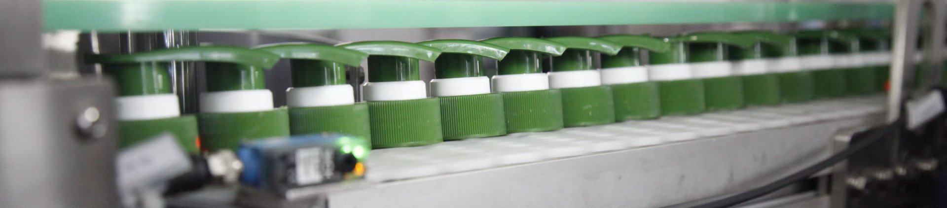
A filling machine and bottle capping machine should be engineered as two connected stations rather than purchased as isolated machines. The filling station controls the filling volume, liquid flow, bottle-mouth cleanliness, and stable transfer to the next process. Weight control should only be specified when the selected configuration includes a weighing or checkweighing function.
The most important engineering work often happens between the end of filling and the start of capping. Foam must settle sufficiently, residual liquid must remain away from the bottle thread, bottles must arrive at a predictable pitch, and the closure must engage its first thread before tightening begins. These conditions also affect whether the capped bottle can move smoothly into labeling, coding, inspection, and carton packing.
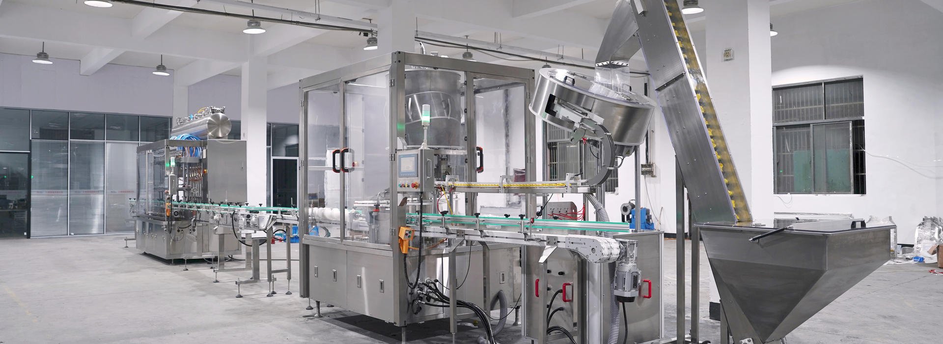
The Process Handoff Between Filling and Capping
The filling cycle does not end when the dosing valve closes. A filled bottle still has to leave the nozzle area, stabilize on the conveyor, maintain the required distance from the next bottle, and arrive beneath the cap-placement or tightening mechanism in a repeatable position.
A bottle can meet the required fill volume and still create capping problems. Foam may continue rising after the bottle leaves the filling station. A viscous product may form a string as the nozzle retracts. Rapid conveyor acceleration may cause liquid movement inside the container. A tall or irregular bottle may rotate before the closure is applied.
The capping station receives the result of all these upstream conditions. It cannot consistently correct a wet thread, unstable bottle, irregular bottle pitch, or closure that has already been placed at an angle. The transfer section must therefore be treated as part of the filling-and-capping process rather than as an unimportant length of conveyor.
Practical purchasing principle: evaluate the filled bottle at the entrance to the capper. The bottle should arrive upright, correctly spaced, sufficiently settled, and free from liquid on the neck or thread that could interfere with closure seating.
Critical Checkpoints Before the Bottle Enters the Capper
1. Foam settlement and available headspace
Foaming liquids may continue expanding after dosing stops. The transfer distance, conveyor timing, filling profile, nozzle movement, and available headspace should allow the product to settle before a closure contacts the bottle mouth. The suitable settings depend on the actual liquid and should be confirmed with samples rather than estimated from product names alone.
2. Bottle-mouth and thread cleanliness
Dripping, splashing, stringing, or an incorrectly positioned nozzle can leave product on the neck finish. Residue may interfere with cap seating, reduce friction consistency during tightening, contaminate the outside of the package, or create problems during later inspection. Anti-drip control, nozzle alignment, filling-end timing, and nozzle withdrawal should be reviewed under real production conditions.
3. Bottle pitch and conveyor synchronization
The capper must receive one bottle at the expected time and position. Irregular gaps can cause missed cap placement, contact between adjacent closures, sensor timing errors, or interruptions at the tightening mechanism. Conveyor speed, bottle-separation devices, infeed controls, and accumulation between stations should work as one synchronized system.
4. Bottle stability after filling
Filled bottles behave differently from empty samples. Their center of gravity changes, internal liquid can move during acceleration, and flexible containers may react differently to guide-rail pressure. Tall bottles, narrow bottles, handled containers, oval bottles, and bottles with offset necks may need additional guiding, side support, neck support, or controlled acceleration depending on the configuration.
5. Closure seating and first-thread engagement
Tightening force should not be applied until the closure is seated correctly. If the cap starts at an angle or does not engage the first thread cleanly, additional torque may only make the defect harder to detect. Bottle centering, cap-placement height, closure guidance, neck-finish consistency, and the initial engagement method should be reviewed before final torque settings are established.
6. Tightening torque and bottle restraint
Torque requirements depend on the bottle neck, closure structure, liner or sealing arrangement, cap material, and product requirements. The bottle must also be restrained sufficiently during tightening without being deformed or marked. Torque values and tolerances should be confirmed with the supplied bottle and cap samples and should not be assumed from another project.
7. Closure and bottle orientation
Some packages require a specific final direction for a trigger handle, dispensing outlet, flip-top feature, label panel, or handled bottle. Orientation may involve the cap feeder, bottle-positioning mechanism, tightening method, or an additional downstream positioning step. The required finished direction and acceptable tolerance should be defined before the line layout is finalized.
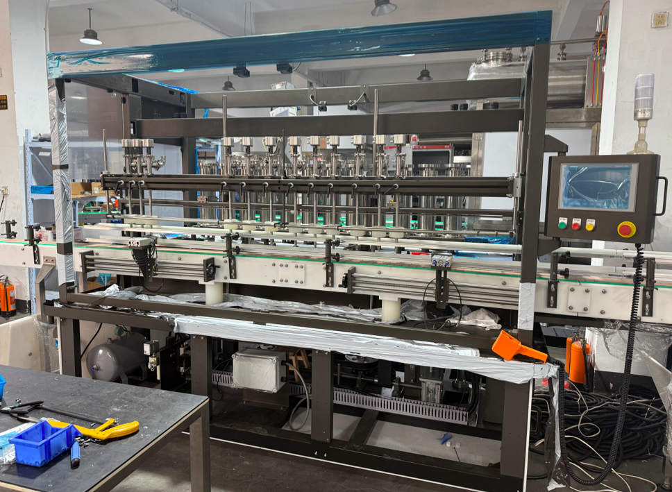 |
Plan Filling Around the Capping EntranceAn inline filling configuration can provide accessible format adjustment and a clear transfer path to the capping station. The final nozzle arrangement, filling method, conveyor controls, and bottle-handling devices should be confirmed from the liquid and package samples. |
Diagnostic Guide: Upstream Filling Symptoms That Appear as Capping Faults
A capping defect is not always caused by the capper. The following diagnostic sequence helps operators and purchasing teams trace a visible closure problem back to the filling station, transfer conveyor, bottle-control mechanism, or capping setup.
| Upstream filling or transfer symptom | Possible capping fault | Parameters or mechanisms to inspect |
|---|---|---|
| Foam continues rising after the bottle leaves the nozzles. | Cap sits high, product reaches the closure, or the bottle mouth is contaminated before tightening. | Filling profile, nozzle depth and movement, headspace, conveyor dwell, transfer distance, and product-specific foam behavior. |
| Nozzle drips or leaves a liquid string during withdrawal. | Wet thread, inconsistent seating, dirty package appearance, or variable tightening behavior. | Nozzle shutoff, anti-drip or suck-back function where configured, nozzle alignment, withdrawal timing, liquid viscosity, and filling-end speed. |
| Bottle spacing changes between stations. | Missed cap placement, cap collision, inconsistent sensor timing, or repeated capper stops. | Conveyor synchronization, bottle separator, timing screw or spacing belts where configured, accumulation pressure, sensors, and transfer gaps. |
| Filled bottle rocks, rotates, or leans during transfer. | Crooked closure, poor first-thread engagement, orientation drift, or bottle rejection at the capper. | Guide-rail position, conveyor acceleration, side belts, base support, neck support, bottle pressure, and bottle behavior under filled conditions. |
| Liquid moves sharply inside the bottle after filling. | Splash reaches the neck, the bottle becomes unstable, or the cap is placed while the package is still moving. | Start-stop profile, conveyor speed changes, transfer height, fill level, bottle geometry, headspace, and spacing between the filling exit and capping infeed. |
| Bottle arrives centered, but the cap starts at an angle. | Cross-threading, high cap, incomplete closure, or excessive tightening load. | Cap-placement height, cap chute or pickup position, closure dimensions, bottle neck finish, centering guides, and the first-thread engagement method. |
| Torque result varies even though the tightening setting is unchanged. | Some closures remain loose while others are over-tightened or visibly marked. | Bottle restraint, neck residue, cap dimensional variation, chuck or belt condition, clutch or servo settings depending on configuration, and cap seating before tightening. |
| The capped bottle exits correctly but enters labeling at an unstable angle. | Skewed label, inconsistent label position, bottle jam, or poor carton-packing transfer. | Cap height, bottle orientation, discharge guide rails, bottle surface cleanliness, conveyor-height transition, and speed matching with downstream equipment. |
Troubleshooting should use filled production samples whenever possible. Empty bottles may not reveal movement, deformation, center-of-gravity, splashing, or guide-pressure problems that appear after the product has been dosed.
Linear Combination Line or Rotary Integrated System?
Both line concepts can connect filling and capping, but they suit different production conditions. The decision should be based on the package range, changeover frequency, required production rhythm, closure complexity, workshop layout, and future expansion plan. Numeric output and accuracy claims should only be added after the actual equipment model and configuration have been confirmed.
A Linear Filling-and-Capping Line May Fit When
- The project includes several bottle sizes or closure formats that require accessible adjustment.
- Changeovers, cleaning access, and direct visibility of each station are important to the operating team.
- The customer wants to add or replace filling, capping, labeling, or inspection modules in stages.
- Production is divided among several SKUs rather than one long, stable run.
- The available workshop supports a straight conveyor layout and separate machine access.
- The target output can be achieved by a confirmed linear configuration after sample evaluation.
A Rotary Integrated System May Be Considered When
- The project has a stable, repeatable bottle-and-cap combination with limited format variation.
- A continuous synchronized production rhythm is more important than frequent format flexibility.
- The closure supply and bottle quality are consistent enough for continuous feeding and handling.
- The production plan justifies a more integrated machine and its related changeover and maintenance requirements.
- Floor-space use, operator access, utilities, and downstream connection have been reviewed as part of the complete layout.
- Real samples can be tested before the final machine arrangement and performance values are approved.
A rotary system is not automatically the better choice simply because the requested output is higher. Package consistency, cap-feeding stability, maintenance capability, changeover expectations, and downstream synchronization can be equally important. A linear system is also not automatically slower or less capable; its performance depends on the selected filling heads, capping method, conveyor controls, and product conditions.
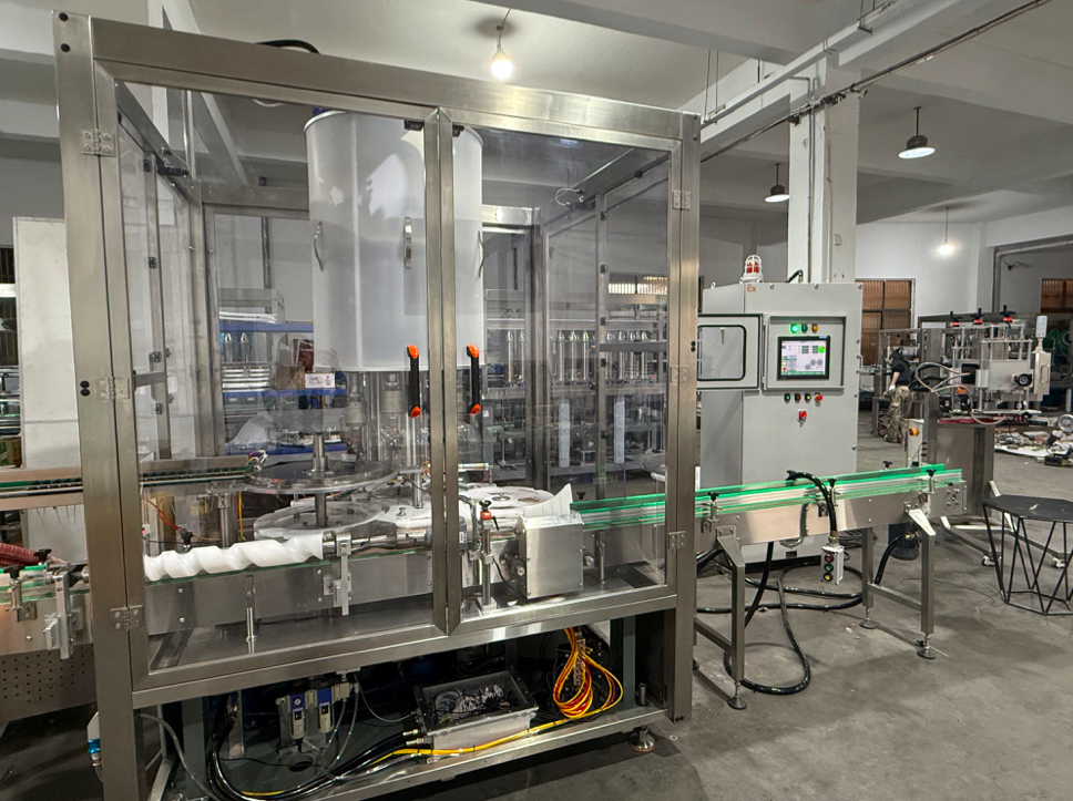 |
Review the Capping Motion With the Full LineRotary capping equipment may support continuous bottle and closure handling, depending on the package and configuration. Selection should be based on the neck finish, cap structure, bottle stability, cap supply, required changeovers, and confirmed production target. |
How the Filling-and-Capping Handoff Affects Labeling and Packing
A bottle is not finished when the cap has been tightened. The capping discharge must deliver a stable package to the next process. Labeling equipment may require a dry bottle surface, controlled bottle rotation, consistent cap height, and a repeatable front panel or handle direction.
Coding and inspection stations need sufficient spacing for sensors and cameras where those devices are included. Carton-packing equipment may require bottles to arrive in a defined lane, orientation, and group size. Uncontrolled accumulation after capping can disturb bottle pitch or allow tall closures to contact one another.
The complete line should therefore be balanced around the slowest stable process, not the highest nominal speed of one machine. Filling output, foam-settlement time, closure feeding, tightening, orientation, inspection, labeling, and packing must all be evaluated together. Final production figures remain subject to the confirmed configuration and sample testing.
Downstream questions to resolve during layout planning
- Must the bottle or closure face a specific direction before labeling?
- Can any product residue remain on the outside of the bottle after filling?
- Does the labeler require continuous bottle movement or controlled indexing?
- Will coding, visual inspection, leak inspection, or checkweighing be included?
- How much accumulation is needed between capping and the next machine?
- Will bottles enter cartons individually, in groups, or through a separate packing conveyor?
- Are future bottle or cap formats expected to use the same downstream equipment?
Which Customers Benefit From Handoff-Focused Line Planning?
This planning approach is useful for brand owners, contract packers, daily chemical manufacturers, personal care producers, household cleaning product plants, and OEM or ODM factories that need filling and capping equipment to operate as one reliable process.
It is especially important when the project includes foaming or viscous liquids, unstable bottles, multiple bottle formats, frequent changeovers, closure-orientation requirements, or direct connection to labeling and packing equipment. Product compatibility and machine configuration should be confirmed through technical review and, where necessary, sample testing.
Multi-SKU Producers
Customers changing bottle sizes, fill volumes, or caps need the full format range reviewed before guide rails, spacing controls, filling nozzles, and capping parts are finalized.
Contract Packers
Frequent product changes make cleaning access, recipe control, changeover parts, sample approval, and realistic performance ranges more important than one theoretical maximum speed.
New Packaging Projects
Customers introducing a new bottle or closure should verify filled-bottle stability, neck cleanliness, first-thread engagement, and downstream orientation before approving the complete line.
Information Needed for a Useful Filling-and-Capping Inquiry
A machine recommendation is more reliable when the technical team can review the liquid, bottle, closure, required process, and downstream connection together. Provide the following information before requesting final output, filling accuracy, torque, or layout values.
- Liquid information: product name, viscosity data if available, foam behavior, temperature, dripping or stringing tendency, and cleaning requirements.
- Filling requirement: minimum and maximum volume, number of products, batch size, and whether any weighing or checkweighing function is required.
- Bottle information: dimensioned drawings, photos, material, neck finish, empty-bottle weight, filled-bottle weight, center-of-gravity concerns, and available physical samples.
- Closure information: cap drawing, thread details, dimensions, material, liner or sealing structure where applicable, required final orientation, and physical samples.
- Production plan: required output range, shift arrangement, expected changeover frequency, and the percentage of production represented by each format.
- Existing equipment: upstream supply system, conveyors, labeler, coder, inspection devices, checkweigher, case packer, and available interface information.
- Workshop conditions: available floor plan, preferred line direction, ceiling height where relevant, utilities, operator access, and maintenance space.
- Acceptance requirements: samples to be tested, closure-quality checks, fill-volume verification method, changeover expectations, and any project-specific documentation that must be confirmed.
Videos of current manual or automatic production can also help identify bottle movement, foaming, closure placement, and downstream handling issues. Any suitability statement remains dependent on the final configuration and the results of technical evaluation or sample testing.
FAQ
Why can a correctly filled bottle still fail at the capping station?
The filling volume may be acceptable while the bottle mouth is wet, foam is still rising, bottle spacing is irregular, or the filled container is unstable. These transfer conditions can prevent correct cap seating and first-thread engagement.
How much distance is needed between filling and capping?
There is no universal distance. It depends on foam-settlement time, conveyor speed, bottle stability, required accumulation, closure placement method, line layout, and downstream connections. The transfer length should be confirmed from the actual process and package samples.
Is torque control enough to prevent loose or crooked caps?
No. The cap must be correctly placed, seated, and engaged with the first thread before final tightening. Bottle centering, neck cleanliness, cap dimensions, bottle restraint, and closure guidance should be checked together with the torque setting.
When should a rotary integrated system be considered?
It may be considered for a stable bottle-and-cap combination, limited changeovers, consistent component supply, and a production plan that benefits from continuous synchronized motion. The final decision should follow layout review, technical parameter confirmation, and sample testing.
Can one linear line handle several bottles and caps?
It may be possible depending on the format range and selected change parts. The technical review should compare bottle dimensions, neck finishes, closure sizes, orientation needs, filling volumes, cleaning requirements, and changeover frequency before compatibility is confirmed.
Can filling speed and capping speed be evaluated separately?
Individual machine capability can be reviewed, but the sellable output of the complete line depends on the slowest stable process. Foam settlement, bottle transfer, cap feeding, tightening, orientation, inspection, labeling, and packing can all affect the final production rate.
Related Equipment and Planning Resources
Liquid Bottle Filling Guide
Review filling methods, liquid behavior, bottle handling, and the information needed before equipment selection.
Linear Filling Machine Category
Compare straight-line filling directions that can be connected with bottle transfer, capping, labeling, and packing equipment.
Rotary Capping Machine Category
Review rotary capping directions for projects that require continuous closure handling and synchronized bottle movement.
Discuss the Complete Filling-to-Capping Process
Send RUN-TECH the liquid information, filling-volume range, bottle and cap drawings, physical samples, required output range, format list, workshop layout, and downstream equipment details. The technical review can then focus on filling behavior, transfer stability, closure engagement, tightening, orientation, and the connection to labeling or packing.
Machine suitability, production capacity, filling accuracy, torque range, and changeover requirements remain subject to the confirmed configuration and sample testing.