
A practical capping line layout cannot be sized from the capper body alone. The working footprint runs from the upstream bottle handoff to the downstream handoff and includes bottle infeed, bottle outfeed, temporary accumulation, cap supply, operator access, maintenance clearance and safe circulation around the equipment.
There is no responsible universal answer to how much space does a capping line need without the actual bottle, closure, neighboring machines and workshop constraints. The correct method is to draw the complete operating and service envelope first, then confirm that the selected capper fits inside it.
|
Check 1
Machine body ≠ total footprint
|
Check 2
Measure handoff to handoff
|
Check 3
Reserve access and buffer space
|
1. Quick Answer: Plan the Working Envelope, Not Just the Machine Body
The capper’s published dimensions are a starting point, not the total floor-space requirement. For reference, Runtech lists its High Speed Automatic Screw Capping Machine at L2200 × W850 × H1650 mm. On a scaled plan, mark the machine and any conveyor length included in that dimension, then measure the additional infeed and outfeed space required between neighboring machines. Allow separately for bottle accumulation, cap supply, operator access, open guards, maintenance and circulation, without counting overlapping conveyor sections twice. Confirm the final footprint against the approved equipment drawing.
Two projects using a similar capping machine can therefore need different workshop space. One may use a simple straight transfer; another may need a turn, extra guidance, a reject station and a cap elevator.
Useful planning rule: approve the machine body, infeed, outfeed, auxiliary equipment and service envelope as one drawing. Do not treat the capper outline as the project footprint.
2. Draw the Capping Line Layout Boundary from Handoff to Handoff
Start at the point where the upstream machine releases the bottle and end where the next process accepts the capped bottle. Those handoff points define the bottle-flow section to be measured, while the full installation envelope must also include equipment and access space extending beyond the conveyor path. Mark the bottle-flow direction first, then add the conveyor centerline, capper position, operator side and maintenance side.
Next, plot fixed constraints: walls, columns, doors, drains, platforms, existing equipment, utility drops and protected traffic routes. A machine may fit inside the open rectangle yet still block cabinet access or a replenishment path.
If the capping principle has not been frozen, review the relevant bottle capping equipment while the floor boundary is still adjustable. Equipment choice and workshop geometry should be checked together rather than sequentially.
The first layout drawing can be simple, but it must be dimensioned. Photos cannot replace measured clearances or available infeed length.
3. Record the Infeed Straight, Bottle Guidance and Buffer Requirements
The bottle infeed has to deliver containers to the capping station in a stable, guided and usable condition. Record the available straight length, conveyor height and width, guide-rail position, bottle direction and the exact interface with the upstream machine. If the concept includes a curve, transfer plate, timing device, screw or starwheel, place that element on the layout instead of assuming it fits inside the capper outline.
Identify why a buffer is needed: to reduce capper starvation, absorb intermittent bottle release or protect another interface. Conveyor length alone does not prove useful accumulation.
Tall, light, narrow or irregular containers may become unstable under back pressure or at guide transitions. Confirm bottle accumulation space for a capper with actual containers when stability is uncertain.
This page is about physical space rather than cycle-rate diagnosis. If the question is whether accumulation will solve starvation or blocking, the separate filling and capping line bottleneck analysis is the better reference for the timing problem.
4. Allow Space for Bottle Outfeed Accumulation, Inspection and Rejects
The bottle outfeed often needs more space than a simple discharge conveyor. Capped bottles may have to accumulate during a short downstream stop, pass a presence or quality check, enter a reject station or transition into labeling, coding or another packaging operation.
Separate normal discharge from outfeed accumulation on the drawing. Discharge clears the capping mechanism; accumulation temporarily stores bottles when the downstream process cannot accept them.
If inspection or rejection is planned, show the sensor, reject mechanism, collection point and operator retrieval route. Do not let a reject bin occupy a maintenance aisle.
Ask one practical question: what happens when the downstream accumulation zone becomes full?
The answer affects sensor positions, stop logic, usable buffer length and where operators need access. Exact buffer capacity should be confirmed during line design rather than taken from a generic conveyor allowance.
5. Position the Cap Supply, Operator Station and Replenishment Route
Bottle flow is only half of the footprint. A cap elevator, hopper, sorter or chute can create a substantial side envelope, so place cap supply on the drawing early and trace the replenishment route.
Operators should be able to replenish caps and reach routine controls without blocking an aisle or service zone. If closures arrive in cartons, bags or bins, reserve staging space near the loading point.
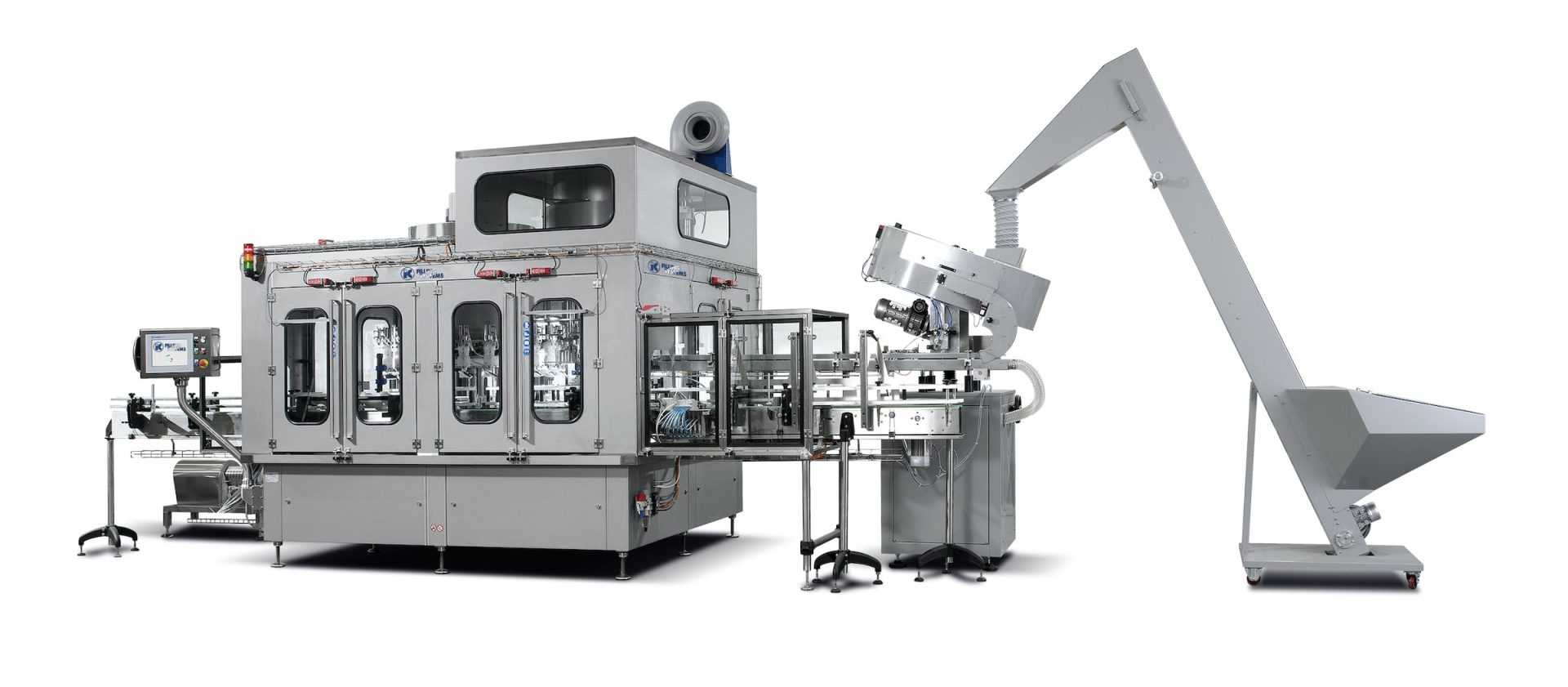
If the project is evaluating filling and capping together, the integrated filling and capping machine product page is a useful equipment reference because it describes bottle feeding, filling, cap handling and finished-product output within one integrated machine concept. The actual site arrangement still needs to be checked against the intended bottle, cap and maintenance requirements.
The operating face should keep HMI access, cap replenishment, bottle observation and routine recovery on a practical side of the machine.
6. Keep Door Swing, Component Removal and Safety Aisles Clear
Maintenance clearance is not just the gap between a machine frame and a wall. It is the working space needed to open guards and an electrical cabinet, reach service points, remove components and move those components away from the machine without colliding with another line or fixed building feature.
Door and guard swing: mark the full open position, not just the closed-machine outline.
Service reach: identify which side technicians need for adjustments, inspection and routine replacement work.
Removal path: check whether the largest serviceable part can actually leave the machine area after it has been released.
Do not apply one generic clearance number unless it comes from the approved machine drawing, the plant standard or the applicable site requirement. Electrical access, mechanical service and pedestrian circulation may require different clear zones.
A layout can be geometrically possible but operationally poor. Review production, operator and maintenance envelopes separately, then check where they overlap.
7. Use a Site Measurement and Photo Checklist
For teams asking how to measure workshop space for capping equipment, start with a dimensioned floor sketch. Use fixed references so the area can be reconstructed later. General photos are helpful, but perspective cannot replace measured distances.
Record these items before requesting a layout review:
- Clear floor length, width and available ceiling height.
- Walls, columns, doors, drains, platforms and overhead obstructions.
- Upstream conveyor centerline, height, width and bottle handoff point.
- Downstream conveyor centerline, height, width and bottle handoff point.
- Bottle-flow direction plus the preferred operator and maintenance sides.
- Proposed cap-feeding position and the closure replenishment route.
- Utility connection locations when they are already fixed.
- Aisle, forklift or other traffic boundaries that cannot be blocked.
Take wide photos from both bottle-flow directions, side views of each interface, fixed obstacles and the ceiling above the proposed station. Include a visible dimension where practical.
For the capping machine infeed and outfeed layout, also send bottle and closure drawings or dimensions. Use representative samples when stability, cap feeding or accumulation behavior is uncertain.
Related reading for a different question
Filling and Capping Line Bottleneck Analysis →
Use this when the problem is starvation, blocking or line-balance accumulation rather than floor space.
Two equipment references after the layout method is clear
After handoff points and access sides are defined, these two product pages provide relevant equipment references. Final compatibility and layout still require confirmation for the actual package and site.
|
Automatic Filling and Capping All-in-One Machine | Full Auto Liquid Processing Equipment Suitable when: filling and capping are being planned as one integrated equipment concept. Why relevant: its page describes bottle feeding, filling, cap sorting, cap pressing and finished-product output. Confirm first: bottle/cap compatibility, handoff geometry and service access. |
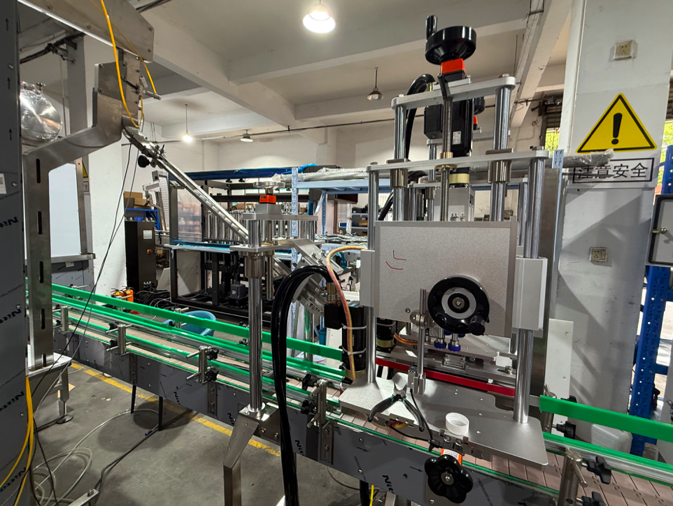
High Speed Automatic Screw Capping Machine Suitable when: an inline screw capper must connect with other packaging equipment. Why relevant: its page describes line connection and matching cap-elevator or cap-sorting equipment. Confirm first: samples, interfaces, auxiliary-equipment position and maintenance access. |
8. Request a Layout Review Before the Floor Plan Is Frozen
A useful RFQ package is a dimensioned project boundary showing where bottles enter, where capped bottles leave and which sides must remain available for operators and maintenance.
Send the floor plan, bottle-flow direction, handoff points, operator and maintenance sides, bottle/closure information, cap-supply position and fixed restrictions. For a retrofit, include the centerline and height of equipment that will remain.
Buyer recommendation: submit a dimensioned floor plan, material-flow direction, operator face, maintenance face and upstream/downstream interfaces. Do not use the machine body size as a substitute for the total project footprint.
A sound capping line layout gives bottle infeed, bottle outfeed, cap supply, operator access and service space the same planning status as the machine itself.
| Explore Capping Machines | Discuss Your Line Layout |
Frequently Asked Questions
Is there a standard infeed and outfeed length for every capping line?
No. Required length depends on the upstream and downstream handoffs, bottle-control method, accumulation purpose, inspection or reject functions and the selected equipment. Use a project-specific layout rather than a generic conveyor allowance.
What information should be sent for a capping-line layout review?
Send a dimensioned floor plan, bottle-flow direction, upstream and downstream interfaces, preferred operator and maintenance sides, fixed obstacles, bottle and cap details and the intended cap-supply location.
How much bottle accumulation space should be reserved before or after the capper?
Reserve buffer space according to the disturbance it must absorb, bottle stability and line-control strategy. A universal length is not reliable. If the question is line balancing rather than physical fit, analyze the actual starvation and blocking behavior.
Should maintenance access be included in the equipment purchase specification?
Yes. The layout approval should identify cabinet and guard opening, service access and component-removal space so the installation is not only physically possible but also maintainable after commissioning.