
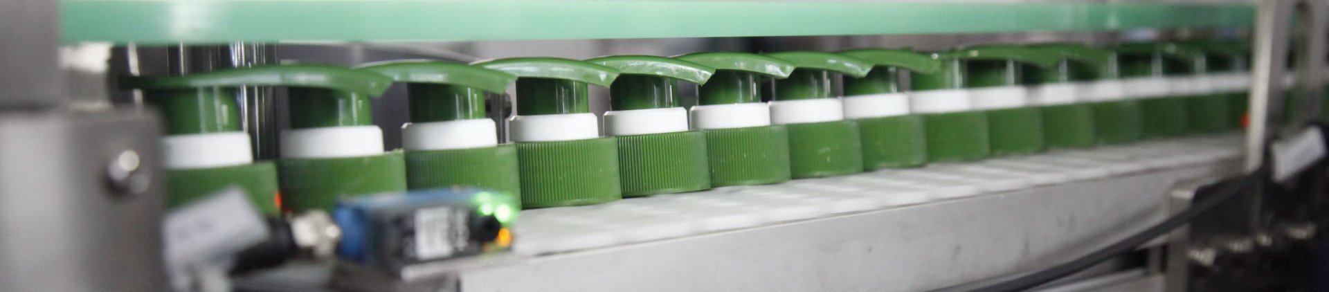
A bottle filling machine changeover checklist should do more than restore one recipe or handwheel position. Changing a bottle format or fill target reconnects container geometry, product behavior, nozzle travel, conveyor control, sensing, and inspection limits. A reliable bottle filler changeover therefore needs a repeatable record covering bottle dimensions, guide rails, nozzle positions, sensors, spacing, dosing values, and trial results. This guide focuses specifically on filling-station setup and release, from initial measurement through dry runs and representative product trials.
Jump to: Changeover Sheet|Bottle Geometry|Nozzles|Rails & Sensors|Fill Volume|Dry vs Product Run|Sign-Off|Application Fit|FAQ
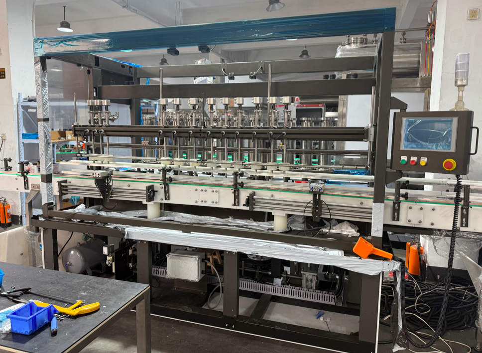
A Runtech linear filling machine with accessible nozzle, conveyor, guide rail, and control adjustment points for multi-format production.
| View Linear Fillers › | Compare Servo Options › |
The four decisions behind a repeatable changeover
|
01
Measure the format Record bottle height, body width, neck center, opening, base behavior, and the stable surfaces available for guidance. |
02
Set the station Restore guide rails, bottle pitch, sensor windows, nozzle spacing, nozzle depth, and the correct filling recipe. |
|
03
Prove the result Separate empty-bottle mechanical checks from representative product, fill-quantity, foam, drip, and cutoff tests. |
04
Release the format Save the approved mechanical positions, recipe revision, reference samples, test evidence, limits, and release status. |
Build a Bottle-and-Fill-Volume Changeover Sheet
A useful changeover sheet starts with one controlled record for every approved SKU and bottle combination. A product name alone is not enough. Two bottles sold under the same nominal size can come from different molds, suppliers, neck-finish revisions, or material specifications. Those differences can affect how the container sits on the conveyor and how accurately the neck arrives below the nozzle.
Each bottle record should therefore link the SKU to a current drawing, controlled bottle code, or approved physical reference sample. Photographs are useful when they show the front, side, neck, base, filling opening, and another clear reference point. A scale or marked datum makes those images more useful during a later changeover. Photographs should support dimensional records rather than replace them.
Bottle material also belongs in the record. PET, HDPE, glass, and other constructions do not behave the same way between guide rails. A flexible container may deform when side pressure is excessive, while a rigid bottle may resist deformation but react poorly to impact or unstable transitions. Wall stiffness and the location of stable guide surfaces can matter as much as overall width.
The sheet should distinguish nominal package capacity from the approved production fill target. A bottle sold as one nominal volume may operate with another internal quantity target to provide the specified headspace or package appearance. Density, temperature, aeration, and the verification method can influence how that target is checked. The approved setpoint should therefore stay tied to a defined test method and acceptance range.
Product behavior needs more detail than a generic description such as “liquid.” Foaming, dripping, stringing, aeration, viscosity, temperature sensitivity, and suspended material can change nozzle and dosing behavior. Record what was actually observed during representative product trials so that a later operator does not assume that two similarly named formulas will behave identically.
Mechanical values require units and datums. “Rail width 80” is incomplete unless the record states whether 80 means an inside gap, a centerline dimension, or a handwheel reading. “Nozzle height 120” has the same problem without a clear starting surface. Every stored value should describe where the measurement begins and ends.
Scales, handwheel counters, fixed gauges, and measured distances can all work as setup references. Their value depends on consistent use. Backlash can produce two different physical positions from the same displayed number, so final adjustment should approach the setting from a consistent direction when the mechanism allows it.
Electronic data should identify the recipe name, recipe revision, fill target, and the settings an operator is authorized to change. Protected engineering limits should remain separate from normal production adjustments. The changeover record should make routine restoration easier without requiring an operator to interpret hidden control logic.
Version control becomes important whenever the bottle supplier, bottle mold, formula, or machine hardware changes. A revised base profile may alter bottle stability even if the commercial bottle description remains unchanged. For this reason, the format sheet should include revision date, bottle/sample reference, approval status, and a brief record of what changed.
Recommended fields for every format record
| Record group | What to capture |
|---|---|
| Format identity | SKU, product name, bottle code, bottle revision, drawing, and approved reference sample. |
| Bottle geometry | Material, wall behavior, height, width, depth, base stability, neck center, opening, and shoulder profile. |
| Product and fill | Nominal capacity, target fill, tolerance source, density, viscosity, foam behavior, product condition, and test temperature where relevant. |
| Handling settings | Conveyor reference, guide rail positions, bottle pitch, stop position, indexing reference, and sensor positions. |
| Nozzle settings | Head count, center spacing, tip type, nozzle height, diving depth, withdrawal behavior, and cutoff settings. |
| Controls and release | Recipe name, dosing values, timing, access level, dry-run result, product-run result, inspection method, and sign-off status. |
The strongest records preserve the reason behind important settings. “Upper rail supports shoulder without neck contact” is more useful than an unexplained handwheel number because it defines the intended physical relationship. If hardware or packaging changes, the team can evaluate whether that relationship still exists.
Close photographs can also support restoration. A useful image shows one setup relationship—such as nozzle-to-neck alignment, rail contact height, or the sensor target—rather than only a wide view of the full machine. Marked reference points make these images especially useful after maintenance.
Bottle Height, Width, Neck Position and Conveyor Stability
Bottle height matters because the filling opening must meet the nozzle path correctly, but total height alone does not define that relationship. Shoulder shape, neck length, neck finish, and base geometry can all change the position of the opening. Measure from the conveyor support surface to the actual filling opening rather than relying only on catalog height.
Width also needs context. A round bottle may be defined by one diameter, while an oval container needs width and depth. Rectangular bottles may contact guide rails at corners rather than across broad flat surfaces. The guide system should be set according to the surfaces that actually control movement through the station.
Inspect the base before tightening rails. Rocker bottoms, molded feet, recessed bases, and uneven seams can make a bottle unstable even when the body dimensions look correct. Small rocking movements can shift the neck away from the nozzle centerline. A stationary placement check should therefore come before the moving conveyor test.
Asymmetric and offset-neck packages require another measurement. The body center and neck center may not be the same. Trigger-style bottles, offset openings, handles, and orientation-sensitive packages need a repeatable arrival direction, otherwise a mechanically centered bottle can still present the opening in the wrong position.
Flexible containers require enough clearance to prevent deformation. Rails that are too tight increase friction and can create intermittent release. Rails that are too loose allow yaw, neck wander, and contact between adjacent bottles. The correct setting guides the bottle without squeezing the body.
Tall, narrow bottles often need support higher on the body. The upper rail still needs a stable contact surface and should not interfere with shoulders, handles, labels, or vulnerable neck details. In this case, rail height can be as important as rail gap.
Short, wide packages create a different limitation. Their openings may sit close to the conveyor, leaving less room for nozzle travel and support brackets. Broad shoulders may also make optical sensing more difficult. Confirm clearances through the complete filling cycle rather than only at the static filling position.
Conveyor stability depends on belt condition, transfer gaps, accumulated pressure, rail transitions, and container spacing. Empty bottles can behave differently from partly filled bottles because their mass and center of gravity change during dosing. Observe entry, stopping, filling, release, and exit as separate conditions.
Normal packaging variation also matters. Sidewall stiffness, molded dimensions, and base behavior may vary within the approved packaging specification. One perfect bottle should not define the entire operating window. Use representative samples when they are available.
Measure geometry from repeatable datums
Use the conveyor support surface as the vertical datum whenever practical. Measure filling-opening height, shoulder height, and maximum body height from that surface. This links bottle geometry directly with nozzle and sensor positions and avoids confusion created by decorative or flexible top features.
For horizontal measurements, define a machine centerline or fixed guide reference. Record both body center and neck center relative to that datum. Offset-neck containers need both values; overall bottle width alone cannot confirm filling alignment.
Check the full stability sequence
Start with a stationary bottle at the intended filling position. Move representative empty bottles through the station without product and observe entry alignment. Confirm that stopping or indexing does not twist the package, then watch release and downstream separation.
Each phase can reveal a different fault. Smooth travel does not guarantee a stable stop when bottles accumulate behind the group. A clean stop does not guarantee that the containers will separate properly after filling. Record the sequence instead of using a general comment such as “runs well.”
Slow jogging can expose contact points and hidden interference, but final confirmation needs the intended operating condition. Normal motion introduces momentum, timing, accumulated pressure, and—in the product run—liquid behavior that may not appear at low speed.
If bottle motion remains unstable, do not correct every problem by tightening the rails. The real cause may be base contact, stop position, belt transition, bottle accumulation, or a poor support height. Follow the bottle from entry through release before deciding which adjustment to change.
Nozzle Position, Diving Depth and Fill-Level Reference
Filling-nozzle setup starts with the bottle opening rather than the machine frame. The tip must enter or approach the opening without striking the neck, shoulder, or internal bottle features. Check every filling head because an aligned first nozzle does not prove that the complete nozzle bank matches the bottle pitch.
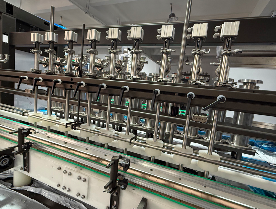
Nozzle centerlines, bottle support points, guide rails, and sensor positions must be restored as one coordinated setup.
| View Linear Filling Machine › |
Nozzle center spacing should match the actual stopped bottle pitch. Nominal conveyor pitch may differ from the final position when bottles compress, rotate, or settle against a stop. Measure center-to-center bottle spacing after the group reaches the filling position and compare the nozzle bank against the same reference.
Opening diameter determines how much alignment tolerance is available. A narrow mouth provides little room for bottle wander or rail variation. A wider opening gives more entry clearance but may still leave the shoulder close to the nozzle body. Check both the opening and the surrounding neck geometry.
Diving nozzles may lower before or during dosing to reduce splash, control foam, or keep the product stream closer to the liquid surface. More depth is not automatically better. Excessive travel can contact the bottle, restrict the available flow path, or place the tip too close to the base.
The lowest nozzle position should remain clear of the base and internal bottle features. The complete travel path must also avoid the neck finish. A controlled manual or dry cycle can confirm these mechanical clearances before product enters the machine.
Withdrawal behavior can affect foam and surface disturbance. For some products, the nozzle rises as the liquid level develops. The useful relationship depends on actual product flow and bottle cross-section, so withdrawal timing should be validated from the observed fill rather than copied from another SKU.
Stationary nozzles still require careful height adjustment. A tip positioned too high can increase splash and falling-stream distance. A tip set too low can strike the neck or leave residue close to the opening. The approved setup should support clean flow and reliable cutoff without package contact.
Nozzle outside diameter, tip profile, anti-drip components, and other product-contact parts also affect clearance. Record the actual nozzle set installed during the trial. Replacing a tip with a different geometry can change the safe position even when the stored height value remains unchanged.
Stringing products add another issue after cutoff. A product thread may bridge between the nozzle and bottle while the container begins to move. Delaying release can reduce smearing but may affect cycle timing and spacing. Evaluate cutoff, bottle movement, and real formula behavior together.
Dripping should not be treated as a nozzle-height problem alone. Product temperature, pressure, valve timing, suck-back behavior, trapped air, and the installed dosing technology can contribute. Only record adjustments that actually exist on the machine being approved.
Define a fill-level reference without confusing appearance and quantity
A visible fill line is useful for comparing bottles quickly, but it does not automatically prove fill quantity. Wall thickness, bottle base geometry, cross-section, foam, and aeration can all change the apparent level. Quantity release should use the approved measurement method.
If visual level matters, define when the bottle should be observed. A foaming liquid may settle slowly, while a viscous liquid may remain on the bottle wall. Comparing a freshly filled bottle with a settled bottle produces false variation. Samples should reach the same agreed condition before visual comparison.
Transparent packaging can also distort the apparent meniscus through curved walls, ribs, molded panels, labels, or lighting. A fixed viewing condition improves consistency but should remain secondary to the approved quantity check.
For opaque bottles, net-weight verification can be practical when tare variation and density are understood. Gross weight alone can be misleading when empty-container weight varies. The sampling and tare method should be defined as part of the quality plan rather than improvised during changeover.
Confirm every nozzle, not only the average result
An overall average can hide one filling head that consistently runs high or low. Trial bottles should remain traceable to their nozzle positions when head-to-head balance matters. A simple head map makes later adjustment and maintenance much easier to interpret.
Look for patterns before changing individual settings. If all heads shift in the same direction, investigate the common setpoint or product-supply condition. If one position behaves differently, the problem may be local to that flow path. This distinction prevents unnecessary changes to every filling head.
Alignment should also be repeated across several cycles. A nozzle that enters correctly once may still experience intermittent neck movement caused by bottle variation, rail vibration, or irregular spacing. Repetition confirms that the geometry is stable rather than correct only for one cycle.
Inspect the bottle finish after the trial. Scuffs, impact marks, wet necks, and residue can expose hidden contact or cutoff issues before they become obvious production rejects.
Guide Rails, Bottle Spacing and Sensor Position
Guide rails establish the container path through the filling station. Their job is guidance, not clamping. The bottle should move without excessive side pressure, uncontrolled yaw, unstable gaps, or unnecessary rubbing against labels and molded surfaces.
Parallel rails work best when the bottle presents stable parallel surfaces. Tapered, curved, handled, or strongly shaped packages may need a different support height or shaped guidance. Choose the contact area that keeps the neck stable without damaging the package.
Rail entry should capture the container gradually. An abrupt narrowing can strike the shoulder, rotate the bottle, or create intermittent jams. An entry that is too open may fail to correct orientation before the bottle reaches the filling position.
At the filling position, guide rails must maintain the intended path during stopping and release. After product enters the container, added mass can change sliding and acceleration behavior. Exit guidance should therefore be checked with filled bottles, not only empty samples.
Bottle spacing affects nozzle alignment, sensor logic, grouping, and release. Containers that arrive too close may appear as one continuous target to a sensor or compress unevenly against a stop. Excessive gaps can interrupt grouping or delay the next filling cycle. Pitch control deserves its own recorded position.
The spacing mechanism depends on machine configuration. Stops, gates, timing devices, or controlled conveyor sections may be used. The format record should identify the actual installed device and its approved setting instead of assuming one mechanism applies to every filling machine.
Sensor position should follow the bottle feature that provides the most reliable detection. Transparent bodies, narrow necks, recessed panels, reflective labels, dark printing, and filled versus empty conditions can change optical response. Test the sensor against the package states it will encounter in production.
A presence sensor should confirm the physical condition required by the control sequence—such as bottle arrival or a complete filling group. Its bracket must also remain secure after cleaning, vibration, and routine contact. Reference marks can help restoration, but functional testing still determines whether the position is acceptable.
Set guide rails from the stable bottle surface
Identify the bottle area that remains reasonably consistent across the production sample. Position the main guide close to that surface without deforming the package. If a second rail level is available, use it to control upper-body movement while avoiding neck, shoulder, handle, and label features that vary more easily.
Check clearance with several bottles rather than one reference piece. The narrowest normal sample should not bind, while the widest sample should not wander excessively. Acceptance should follow the approved bottle specification rather than an arbitrary “tight” or “loose” setting.
Repeated travel can reveal friction marks that are not visible in one pass. Scratching, label damage, or residue buildup may show that the apparent rail gap is not working as intended. Final trials should use a cleaning condition comparable to normal production.
Confirm spacing as a moving pattern
Observe spacing before, during, and after the filling stop. Bottles should reach the control point without damaging contact, remain correctly positioned under their intended nozzles, and leave without bunching or collision.
Accumulation changes the forces acting on the group. An empty infeed section may operate cleanly while accumulated bottles push the leading containers out of orientation. Include realistic upstream pressure in the test where the machine design and safe procedure allow it.
Do not use conveyor speed as the only correction for unstable spacing. Stops, sensor position, timing, rail friction, and the bottle base can all influence the pattern. A speed reduction may hide one symptom while moving the problem elsewhere.
Prove the sensor window, not just one switching point
Move representative bottles through the sensing area during controlled setup and identify the range over which detection remains reliable. Compare that window with normal bottle movement and stopping variation. A very narrow sensor window indicates limited tolerance even if one sample switches correctly.
Test expected package differences such as label presence, bottle color, transparency, and product inside the bottle. The objective is not to create unrealistic extremes but to prove the approved production range.
The no-bottle condition should also be challenged according to the machine’s safe operating procedure. Filling permission must remain blocked when the required bottle state is absent. This test should be completed and documented before production release.
What Must Be Rechecked When Fill Volume Changes
A new fill volume is more than a number entered on the control screen. The changed target can alter dosing time, product velocity, nozzle immersion, headspace, settling behavior, and the mass of the container during release. Every meaningful volume change therefore needs a focused recheck.
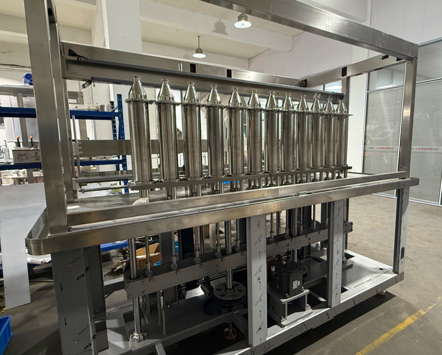
A servo piston assembly should be evaluated with the actual product, bottle, fill range, and quantity-verification method.
| View Servo Filling Machine › |
Confirm first whether the bottle geometry remains unchanged. One container may be used for several fill targets, in which case the mechanical rail positions may stay valid while dosing, level reference, and inspection criteria require separate recipes. The changeover record should clearly distinguish retained mechanical settings from values that need new evidence.
Confirm the exact formula linked to the target. Products with similar commercial names can differ in density, viscosity, foam, aeration, and cutoff behavior. Color and opacity can also change the usefulness of visual inspection. A fill-volume recipe should therefore remain tied to a defined formula condition.
If the project is still deciding between different filling principles, review the separate guide to filling route selection for piston, pump, flow-meter and weighing applications. That decision belongs upstream of this changeover procedure. Once the filling method is defined, the present checklist is used to restore and validate the selected configuration.
Product-supply conditions can also affect dosing consistency. Tank level, pressure, temperature, trapped air, and refill demand may change the result depending on machine design. Trials should reproduce the intended production supply condition as closely as practical.
Priming is especially important after cleaning, product change, maintenance, or extended stoppage. Air or cleaning liquid inside the product path can distort the first samples. The approved procedure should define when the system is considered stable enough for formal verification.
Define the controlling quantity method clearly. Volume, net mass, visible level, and another approved control are not interchangeable measurements. If density is used to connect mass and volume, the value should match the actual tested product condition rather than an unrelated formula or temperature.
Container tare variation can also influence net-weight checks. Using one assumed empty-bottle weight may make normal packaging variation appear to be fill variation. The accepted tare and sampling method should already be defined in the quality plan.
Recheck the dosing setpoint and related timing
The main dosing setpoint can represent different physical controls across filling technologies—motion, time, flow, weight, stroke, or another configured parameter. Use the machine’s actual control terminology in the record rather than a generic description.
A changed target may also affect valve timing or motion synchronization. The bottle must still be confirmed in position before dosing begins, and cutoff must finish before release. Larger fills can extend the active filling period enough to change this timing relationship.
Smaller fills can expose another behavior because the product may spend less time close to the nozzle. A high initial flow may splash or aerate the product more strongly. Larger fills may bring the liquid surface much closer to the nozzle tip. Observe the complete dosing cycle rather than only the final quantity.
Recheck nozzle depth, withdrawal and cutoff
A diving depth approved for one target may not suit another. A low fill can leave the nozzle unnecessarily deep relative to the final surface. A higher fill may require a different withdrawal relationship to control splash or foam. Store volume-specific nozzle programs where the process needs them.
Observe the last product leaving every nozzle after cutoff. Drips may land on the neck, shoulder, conveyor, or following container. Excessive suck-back can create its own problems by drawing air or disturbing the next dose. The correct balance must be proven with the production formula.
Check residue after repeated samples. Some viscous or stringing products accumulate droplets gradually, and temperature can change the pattern as the run continues. One clean bottle is not enough evidence if the problem develops over several cycles.
Recheck headspace, foam and settling
Headspace should follow package and product requirements rather than a visual preference for a “full” bottle. Foam can temporarily occupy the headspace and hide the true liquid surface. A bottle may look overfilled immediately after dosing and become correct after settling—or appear correct initially and settle lower later.
Aeration can also affect density and volume readings. Use a defined sample condition and consistent delay before inspection when the product traps air. Do not apply one universal settling time to every formula.
Recheck every filling head after the volume change
Individual outlets can respond differently when the target changes. A nozzle bank that appears balanced at one fill volume may expose timing or flow differences at another. Keep samples traceable by head position when balancing matters.
Start with a stable, properly primed sample set and compare each outlet against the approved measurement method. Investigate a local difference before changing common settings. When every head shifts together, look first at shared setpoints or supply conditions.
Repeatability is more important than one accepted group. The required sample count and tolerance should come from the project quality requirements, not from a generic number applied to every product.
Recheck recipe identity and restart handling
A newly approved volume should have a controlled, recognizable recipe name. Similar free-form names increase the risk of loading the wrong program. Use a SKU or another controlled identifier and protect approved values from casual overwriting.
Restart conditions also deserve attention. An interrupted cycle may leave full, partly filled, or empty bottles inside the station. The approved machine and production procedure should define how uncertain containers are identified and removed before the line restarts.
Dry Run vs Product Run
A dry run proves mechanical movement without dispensing the production formula. It can reveal guide-rail interference, bottle tipping, sensor gaps, nozzle collisions, unstable stopping, and spacing problems. It cannot prove fill quantity, foam behavior, dripping, stringing, or final package cleanliness. The two tests answer different questions.
Before the dry run, remove adjustment tools and loose items from the station. Move bottles through entry, indexing or stopping, filling position, release, and exit using the approved safe procedure. The objective is controlled observation rather than maximum production speed.
Watch every container contact point. Scraping, sudden rotation, rocking, neck movement, or delayed release indicates that setup is not complete. Listen for impacts that may not be obvious from one viewing angle.
Sensor checks belong in this stage. Bottles should create the expected detection sequence across normal spacing variation. Missing or incorrectly positioned bottles should not generate unintended filling permission.
Nozzle alignment can also be confirmed with empty bottles. A perfect dry mechanical cycle is necessary, but it is not production approval. Real product must still prove dosing, foam, cutoff, settled quantity, and filled-container behavior.
|
ADry run can prove
|
BProduct run must prove
|
Water can support selected engineering checks when the procedure allows it, but water may behave very differently from a foaming, oily, viscous, or stringing production formula. Density and surface tension can differ as well. Water should not automatically become approval evidence for every product.
A representative product run should use the intended bottle, nozzle set, product-contact parts, fill target, and inspection method. Product condition should fall inside the planned operating window as closely as practical. Record any meaningful deviation from the intended condition.
Before formal sampling begins, the product path should reach a stable condition. Air pockets, cleaning liquid, or mixed formula can distort early results. The correct preparation method depends on the machine and product, so the approved procedure should identify when verification samples become valid.
Observe the complete fill—from initial flow through final cutoff. Splash may appear immediately, foam can build during the dose, and dripping often appears only after the valve closes and the bottle begins to move. Treat these as separate observations.
Filled bottles need another stability check. Added mass can improve base contact but increase stopping momentum. Product on the bottle neck or conveyor can also change friction. Include release, transfer, and local cleanliness in the product trial.
Compare dry-run findings with product-run evidence
Keep both tests in the same issue log. A dry run can show perfect centering while real product flow creates new bottle movement. A quantity problem may also appear even though the mechanical cycle is stable. Linking the observations helps identify whether the next adjustment belongs to geometry, controls, product supply, or dosing.
When a product-run fault appears, avoid changing several controls at once. Record the symptom, suspected cause, adjustment, retest, and result. Failed settings are useful evidence as long as they remain clearly separated from released values.
Pre-Production Sign-Off Checklist
Sign-off converts the changeover trial into a controlled production decision. The SKU, bottle revision, formula, fill target, mechanical positions, recipe, and inspection evidence should all refer to the same approved condition. A signature alone cannot compensate for missing or conflicting evidence.
Release rule: the new format is ready only when the mechanical setup, control settings, representative product results, and saved record describe the same approved condition.
| Check area | Release evidence |
|---|---|
| Mechanical setup | Correct bottle revision; measured height, neck center and opening; approved rail positions; bottle pitch; stop position; nozzle center and safe travel clearance. |
| Controls & sensors | Correct recipe loaded; fill target confirmed; sensor window proven; no-bottle protection checked; temporary test overrides removed. |
| Product run | Representative formula condition; stable priming; approved quantity method; head balance where required; foam, splash, drip, stringing, cutoff and filled-bottle release observed. |
| Record & release | Final values stored with units and datums; drawings and sample references linked; rejected settings kept separate; open limitations identified; approval date and status recorded. |
The decision should be clear: release, hold, or conditional release under an approved process. Comments such as “mostly acceptable” do not define what production is allowed to do. Any open condition should include its limit, responsible owner, and required verification.
When the same format returns later, the approved record becomes the starting point rather than a substitute for confirmation. Maintenance, nozzle replacement, sensor movement, and packaging revisions can change the physical result even when the displayed settings remain identical.
Turn Approved Changeover Data into a Repeatable Setup Standard
The final changeover standard should preserve the relationships that made the trial successful, not just the final numbers. Keep the bottle drawing or sample reference, measurement datums, product condition, approved mechanical positions, recipe revision, and the corrections that solved important faults.
Group SKUs only when evidence shows that they truly share a mechanical format. Two labels may use the same bottle and rail setup while requiring different filling recipes because viscosity or fill target changes. Separate common mechanical data from product-specific dosing controls.
When evaluating the complete SKU range, do not assume that the tallest and shortest bottles are automatically the hardest formats. An offset neck, unstable base, narrow opening, flexible sidewall, or difficult product may create the tighter operating window. The most difficult format should be included in the technical review.
Failed trials can remain useful when they are clearly marked as rejected. A rail position that caused bottle rotation or a nozzle depth that increased foam helps explain why the released setting was chosen and prevents the same unsuccessful adjustment from returning later.
When a Controlled Changeover Process Matters Most
A structured changeover process is most valuable in high-mix production where the filling line must return repeatedly to approved bottle formats, fill targets, or formulas. Typical examples include personal-care products, household liquids, and contract or private-label production where several SKUs share one line.
| Production pattern | Why changeover control matters |
|---|---|
| Multiple bottle formats | Rail height, bottle pitch, neck position, sensor windows, and nozzle clearance must return to controlled positions. |
| Multiple fill targets | Dosing values, timing, nozzle movement, headspace, foam, and the quantity-verification method may change even when the bottle is unchanged. |
| Contract / private-label filling | Frequent SKU changes make documented settings and representative sample trials more reliable than operator memory. |
A stable single-format line running one product continuously may place less emphasis on repeated format restoration. Corrosive, flammable, strongly oxidizing, solvent-based, or otherwise hazardous products also require a separate materials, process, and safety review beyond the scope of this checklist.
Prepare the Format Package for Technical Review
Before requesting a machine or changeover review, prepare the primary bottle photographs or drawings, bottle height, body width, neck-center position, opening size, fill-volume range, SKU list, target output, and representative bottle samples. Identify the least stable bottle, the most offset or narrow opening, the most sensitive formula, and the expected changeover sequence. These details allow Runtech to compare the real format range with suitable linear or servo-controlled filling configurations and define the sample-test conditions that should be verified before production.
- Measure bottle height, body width, neck center, filling opening, base behavior, and stable guide surfaces.
- List each fill target and formula condition that may require a separate recipe or nozzle program.
- Identify the most difficult bottle and the product most likely to foam, drip, string, or create filling variation.
- Submit the SKU matrix, bottle drawings, representative samples, target output, and expected changeover frequency for technical review.
| Submit Format Details › |
Bottle Filling Machine Changeover FAQ
Which bottle should be used as the worst-case changeover sample?
Do not choose only by maximum or minimum bottle size. The most useful worst-case sample may have an offset neck, narrow opening, flexible wall, unstable base, difficult guide surface, or another geometry that leaves the least alignment margin. A representative technical review should include the format that places the greatest demand on guidance, sensing, and nozzle clearance.
Can two SKUs share mechanical settings but use different filling recipes?
Yes. Two products may use the same bottle geometry, rail positions, sensors, and nozzle spacing while requiring different dosing values, cutoff behavior, nozzle movement, or inspection conditions. The format standard should separate common mechanical data from formula- and fill-target-specific recipe values.
When should a new format remain on hold instead of being released?
Keep the format on hold when key evidence is missing or inconsistent—for example, when the final bottle revision is unavailable, nozzle clearance is not repeatable, sensing is unstable, representative product has not been tested, quantity results fall outside the approved method, or temporary troubleshooting values have not been converted into a controlled recipe. Release should follow evidence, not the planned production date alone.